
Specifications


Installation and Operation Manual
●
Fan Coil Controller – EZstat
EC-EZstat
Date: 9-2014 Supersedes: NEW
Engineered Comfort reserves the right to change any information concerning product or specification without notice or obligation.
Page 11 of 36
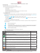
ConnecngtoOn/Ovalves
The following diagram shows the connecons for an on/o valve.
• The valves are actuated by 24 VAC
• The outputs are 24 V relays.
Fig.4-7Connecng
on/ovalve
COM
R
B05
4.4 ConnecngPower
The EZstat requires an external, 24 VAC power source. Use the following guidelines when choosing and wiring
transformers.
• Use only a Class‑2 transformer of the appropriate size to supply power.
• Connect the transformer’s neutral lead to the COM terminal.
• Connect the AC phase lead to the 24VAC terminal.
• Power is applied to the controller when the transformer is powered.
Fig. 4-8 Wiring for EZstat power
COM
24VAC
4.5 Maintenance
Remove dust as necessary from the holes in the top and boom. Clean the display with so, damp cloth and mild soap.