2/9/2007 IP PBX Administration Guidelines MAG-07003 Rev. B IP PBX Administration Guidelines Version 1.
TABLE OF CONTENTS 1 2 Introduction ....................................................................................................................................... 1 1.1 Overview .......................................................................................................................1 1.2 Platform Category ......................................................................................................... 2 1.3 Installation ...................................................
2.9.2 SIP UA.................................................................................................................. 9 2.9.3 CDR Log............................................................................................................... 9 2.9.4 System Events...................................................................................................... 9 2.9.5 Active Calls........................................................................................................
IP PBX Service............................................................................................................16 3.6 3.6.1 Service & Configuration......................................................................................16 3.6.1.1 Reload IP PBX Configuration ....................................................................16 3.6.1.2 Backup IP PBX Configuration....................................................................16 3.6.1.3 Restore IP PBX Configuration .......
4.4.3 4.5 Route Group Configuration .........................................................................................31 4.5.1 Add a Route Group ............................................................................................32 4.5.2 Edit a Route Group.............................................................................................32 4.5.3 Delete a Route Group ........................................................................................32 4.
5.4.2 Edit a MOH File ..................................................................................................48 5.4.3 Delete a MOH File..............................................................................................48 5.5 Voicemail.....................................................................................................................48 5.6 Meet-me Prompts (PC#1, PC#2, PC#3 only) .............................................................50 5.
1 Introduction 1.1 Overview The IP PBX Administration Guide provides instructions for administering the IP PBX system. IP PBX is an embedded call-processing server communicating with client stations with Session Initiation Protocol (SIP). It migrates the telephony network and the data network of a small-to-medium business (SMB) company into a manageable converged network.
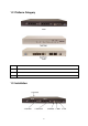
1.2 Platform Category PC#1 PC#2 PC#1 ETX-1825, ETX-1823 PC#2 ETX-1802, ETX-1801 PC#3 ETX-1800MXD, ETX-1800MX PC#4 ETX-1800 1.
1. AC Power 100-240 V, 50-60 Hz 2. POTS ports Usually 4 ports per daughter card, numbered from right to the left. The rightmost port at slot 0 is port 1 and the leftmost port at slot 1 (if installed) is port 8. FXO ports are to be connected to FXS jacks on wall or analog PBX using RJ-11 cables. FXS ports are to be connected to analog phones, fax machines, or FXO ports of other devices. ISDN BRI TE ports are to be connected to NT points from PSTN or other ISDN network-side devices. 3.
2 System Configuration This section describes how to configure system parameters used by IP PBX. The factory default of LAN IP address is 192.168.1.1. Connect to LAN port and the configuration Web interface is at https://192.168.1.1/. Once connected, the browser will ask for accepting a certificate. Click Yes to see the home page. Type in the default administrator ID and password (both are admin) to log in for administration. The administrator password can be changed in the User Management -> User. 1.
2.3 On-board WAN Setup The On-board WAN Setup page allows administrator to configure WAN network interface for IP PBX. Select System -> On-board WAN Setup, and the current setting of WAN network interface is displayed, e.g. type, IP address etc. Unless the LAN Only is selected, you can choose one of the three options, Static IP, DHCP, and PPPoE from the Type list for your configuration. Select LAN Only check box to disable WAN, and only default router and DNS settings are applicable.
2.3.5 MAC Clone Select MAC Clone and enter a MAC/physical address to change the WAN MAC address. 2.4 On-board LAN Setup The On-board LAN Setup page allows administrator to configure LAN network interface for IP PBX. 1. Select System -> On-board LAN Setup to see the current settings of LAN network interface. 2. Enter a new IP address and network mask. 3. Click APPLY to change the settings.
2.5.3 Delete a Route 1. Select a route ID. 2. Click DEL to remove the route ID from the IP Route ID column. 2.6 Dynamic DNS Setup Dynamic WAN IP address causes difficulty for inbound connections from remote clients or IP PBX systems. A popular work-around is to adopt domain names provided by Dynamic DNS service providers and run a client on or behind the gateway router (or IP PBX). It is required to apply an account and create a hostname in the account before configuration.
2.7.1 Enable QoS 1. Click Enable 2. Enter the WAN Uplink Speed, WAN Downlink Speed, and Uplink VoIP Reserved (bandwidth). 3. Click APPLY. For a popular 2M/256K ADSL program, the WAN uplink speed would be 256 and the WAN downlink speed would be 2048. The Uplink VoIP reserved could be, say, 192 out of the total 256 kbps to allow 2 concurrent G.711 calls. 2.7.2 Disable QoS Click Disable, and then click APPLY. 2.
2.8.3 Delete a Service 1. Select a service ID. 2. Click DEL to remove the service from the Service ID. 2.9 Maintenance This page includes maintenance functions of IP PBX, including Storage Backup, SIP UA, CDR Log, System Events, and Active Calls. 2.9.1 Storage Backup To back up internal main storage, click BACKUP, and follow the instructions to insert the USB connector of an external USB drive. Options include whether to keep or remove CDR and/or voicemails after backup.
2.9.5 Active Calls The Active Calls page shows current active calls. Columns Client and Party indicate the involved extensions or trunks of a call. State shows the state of a call, while Service gives the current action of the listed Client. Field Description Client Show the caller or callee’s extension number, port number, or SIP trunk ID. State Service Connected In the conversation. Ring The client is a caller and is ringing a callee. Ringing The client is a callee and is ringed by a caller.
2.11 Shutdown In System -> Shutdown, you can shutdown the machine by clicking YES, or reboot the machine by selecting the Rebooting After Shutdown check box and clicking YES. In case the software reboot fails, you can also press the hardware Reset button. It is advised to shut down IP PBX system before a power-off. 2.12 Logout Logout button locates at the top-left of the webpage. Administrator can logout, and go back to the login page by clicking it.
3 Service Configuration This section describes details to configure various services built in the IP PBX. 3.1 NTP Service Select Service -> NTP Service to specify a NTP server for network time synchronization. You can enable or disable NTP service at any time. 3.1.1 Enable NTP Service 1. Click Enable. 2. Select Automatic check box to use server pool at pool.ntp.org; or, enter a fully qualified domain name or the IP address of a NTP server. 3. Click APPLY. 3.1.
3.3 STUN Service IP PBX has a built-in STUN client to solve NAT problems. Select Service -> STUN Service to specify a Simple Traversal of UDP through NATs (STUN) server for NAT traversal. You can enable or disable STUN Service at any time. Note: You have to restart the IP PBX Service, after changing the STUN setting. 3.3.1 Enable STUN Service 1. Click Enable. 2. Enter a fully qualified domain name or the IP address of a STUN server. 3. Click APPLY. 4.
created under /. yet. 3.4.1.2Add a Folder 1. Click a directory under which you want to add a new folder in the Directory list. 2. Click ADD FOLDER. 3. Enter a folder name in the pop-up dialog box, e.g. myfolder. 4. Click OK to see the newly added folder in the Directory list, e.g. /myfolder/. 3.4.1.3Delete a Folder 1. Click a directory of a folder in the Directory list. 2. Click DELETE FOLDER to remove the folder from the Directory list.
3.5 DHCP Service Select Service -> DHCP Service to view the current status of the DHCP Service. You can enable or disable the DHCP Service at any time. Note: If the IP PBX was shut down abnormally, Select Service -> DHCP Service and click APPLY, or Go to Service -> IP PBX Service, and click RESTART to active the DHCP service. 3.5.1 Enable DHCP Service Click Enable, choose the main interface offering addresses, and then APPLY to configure DHCP settings. 3.5.1.1Add DHCP Range 1. Click CLEAR. 2.
3.5.2 Disable DHCP Service Click Disable, and click APPLY. 3.6 IP PBX Service In Service -> IP PBX Service, you can click the Service & Configuration tab to reload, backup, restore, restart or revert the IP PBX configuration, or click the Advance tab for the IP PBX parameters settings. 3.6.1 Service & Configuration Select Service -> IP PBX Service, and then click the Service & Configuration tab. 3.6.1.
factory default. Note the reversion affects IP PBX service only, but not other system services such as DHCP, TFTP, and NTP. The backup IP PBX configuration files under TFTP remain intact after reversion, so that one can restore to a specific time if a backup file had been generated then. To revert the whole system back to the factory default as much as possible, hold the hardware Reset button for 10 seconds.
clients or even SIP trunks fail due to such change. Clear the box if you are not sure. Max Active Users Enter a number for registration admission control to limit the maximum number of active registered clients. Max Active Calls Enter a number for call admission control to limit the maximum number of concurrent calls. Max Wireless Calls Enter a number to limit the calls made by explicitly specified wireless extensions.
4 IP PBX Configuration This section introduces steps to provision the IP telephony part of the IP PBX. Note that reloading configuration is required in order to make new configuration effective 3 . 4.1 User Configuration A user is a logical entity in IP telephony which associates extensions with a usergroup. It also propagates its attributes such as e-mail and voicemail PIN to extensions.
Table 4.1 User configuration Settings Field Description Login ID A unique ID containing alphabets, numbers, and underscore only without spaces; 32 characters maximum. This is the ID for personal configuration through IP PBX Web management. Name Name of the user, either a real or a virtual one, e.g. Alice Lee or Conference Room. Password Password for the user to access IP PBX Web management. Description Arbitrary description information.
4.2.1 Add a User Group 1. Enter a usergroup name beside the ADD button, and then click ADD. 2. The name will show in Group ID. 3. Click the name in Group ID to view the edit page. 4. Enter settings shown in Table 4.2. 5. Click SET to save the settings, and click BACK to return to the USERGROUP MANAGEMENT page. Now, you can see the newly added usergroup displayed in the Group ID. 4.2.2 Edit a User Group 1. Click a usergroup name in the Group ID. 2. Edit settings shown in Table 4.2. 3.
balance group for an outgoing call. ) Trunks with the same group ID must be put together, or the function will not work. ) If there is not any appropriate SIP trunk and PSTN trunks to select, come back later to revise selection once trunks have been created. Reachable User Groups Select other usergroups reachable from this usergroup. By default, only users in the same usergroup can reach one another.
4.3.1 IP Phone The DEVICE PHONE MANAGEMENT page lets the administrator to create IP Phone devices. Before a device can be reached from the IP PBX, the same account information has to be programmed into the device through the configuration interface enabled by the device. Select Device -> IP Phone to add, edit, and delete devices. Go to Service -> IP PBX Service, and click RELOAD to activate changes. 4.3.1.1Add a Device 1.
Codec Preference Preference order of supported codec and packet times of the phone. VAD is a technique that detects absence of audio and conserves bandwidth by preventing the transmission of Enable Voice Activity Detection (VAD) "silent packets" over the network. ) Select if your IP Phone supports VAD. DTMF mode Choose a DTMF mode used by the phone 4.3.2 Extension of IP Phone The EXTENSION MANAGEMENT page lets the administrator to create extensions.
configuration side. Associated Device Select the Device this extension associates with. Password Password of this extension. Same password must be configured on the device side as well. User 6 Select the user this extension associates with. ) If there is not any appropriate users to select, one can come back later once the expected user has been added. Pickup Group The usergroup that the extension can pick up.
enable this since other DTMF modes require IP PBX being RTP relay server to support in-line transfer. DTMF Mode Choose preferred DTMF mode for this extension. Currently supported types include RFC2833, SIP INFO, and in-band tone. It must match configuration on the device side. ) In-band DTMF mode consumes the limited DSP resource when using a highly compressed codec, such as G.729 or G.723.1. Therefore, calls will not connect with such setting if DSP is not installed.
Timeout To Next Forward (Optional) Enter a period of time in seconds for rings the extension in Unavailable Call Forward. Click to add the extension in Unavailable Call Forward and the time here into the list. Remove the extension of Unavailable Call Forward from the list by clicking Play Unavailable Forward Prompt . (Optional) Notify the caller that callee is not available and the call is being forwarded to another extension.
3. Click UPDATE. 4. Click BACK to see the edit information. 4.3.3.3Delete an Analog Phone 1. Select a POTS Port. 2. Click DEL to remove the extension from the POTS Port. Table 4.3.3 FXS Extension Configuration Settings Field Description POTS Port FXS port index. Extension Number A unique line number composed of digits only, e.g. 101; 32 digits maximum. Pickup Group The pickup group that the extension belongs to. Unavailable Timeout Timeout for ringing before a call is answered.
Selective Call Blocking (Optional) Select Block Anonymous Calls to block all calls without a Caller ID (Optional) Block one or more calling numbers by typing the calling numbers and clicking . Removing the blocked numbers by clicking the number from the list, and then click . Forward Options (Optional) Select Unconditional Call Forward and click a default destination in the list, e.g. Voicemail or Phone Number.
4.4 Route Configuration A route is a destination number pattern for outbound call matching. A pattern consists of digits 0-9 (including “-”), “*”, “#”, digit set, and wildcard characters like “.”, “X”, “Z”, and “N”. Table 4.4.1 explains digit set and wildcard characters. Note: The “#” in route patter is for some PSTN saver lines that may set “#” as their dial pattern. For most of the IP Phones, press “#” will send out the dialed number. Table 4.4.
4.4.3 Delete a Route 1. Select a Route ID. 2. Click DEL to remove the route from the Route ID. Table 4.4.2 Route Configuration Settings Field Description Route ID A unique ID containing alphabets, numbers, and underscore only without spaces; 32 characters maximum. Description Arbitrary description information. Destination Number Pattern A destination number pattern consisting of digits, digit set, and wildcard characters, e.g.
routegroups in the ROUTE GROUP MANAGEMENT page. Go to Service -> IP PBX Service, and click RELOAD to activate changes. 4.5.1 Add a Route Group 1. Type a route group name and click ADD. 2. Click the route group in Group ID to see the settings. 3. Enter settings shown in Table 4.5, and click BACK. The newly added route group should be displayed in the Group ID. 4.5.2 Edit a Route Group 1. Click a route group name in Group ID. 2. Edit settings shown in Table 4.5. 3.
can come back later to revise it, once the expected routes are added. 4.6 SIP Trunk Configuration A SIP trunk refers to a SIP account on a remote call routing or gateway device. A practical example is an account at an Internet Telephony Service Provider (ITSP) where a call is routed to a SIP client or off-ramped to an analog subscriber via PSTN. One could also build SIP trunk to a remote IP PBX to reach its extensions and PSTN ports.
Description Arbitrary description information. Dynamic Peer Select if the trunk is a passive trunk which means the registration will be from a dynamic remote peer. Typical application is to accept registration from an IP PBX at a remote site with dynamic IP address. Once the remote IP PBX registers, calls from local to remote can be made reversely over the trunk.
directed to the corresponding extension derived by number manipulation. The SIP trunk numbers is therefore regarded as the direct line of the extension. ) If you set a DID extension in a trunk, then only that extension can use this trunk to call out, and all incoming calls to this trunk will connect to that extension directly. ) If selecting By Number, the "number" being manipulated for extension DID is the called (destination) number.
Advanced Settings Select to see more settings shown below. DTMF Mode Select a preferred DTMF mode, RFC 2833 or SIP INFO, for this trunk in the list. This must match configuration on the server side. If the user does not know the DTMF mode on the server side, select Not Sure from the list, and SDP will automatically detect the DTMF mode is Inband or RFC2833. Try Peer-to-peer RTP Click NO to disable or IP PBX will attempt to notify the two peers in a conversation to try peer-to-peer RTP transmission.
4.7 Analog PSTN Trunk configuration (PC#1, PC#2 only) An Analog PSTN trunk group is a logical group of one or more FXO or FXS PSTN subscriber lines connecting to FXO and FXS ports on IP PBX. The ANALOG PSTN TRUNK MANAGEMENT page allows the administrator to configure PSTN trunks. Select Trunk -> Analog PSTN Trunk, and one can add, edit and delete PSTN trunks. Go to Service -> IP PBX Service, and click RELOAD to activate changes. 4.7.1 Add an Analog PSTN Trunk 1. Click the Add New tab. 2.
Trunk Ports FXO and FXS port indices grouped by this PSTN trunk, such as 1 or 1,2 or 1-3, etc. Maximum port index depends on the number of physical ports available. Description Arbitrary description information. Port Selection Click to search for an available port in the group. Rotating means to force ports being selected by turns to even cost. Caller ID Detection Select to detect the Caller ID calling from PSTN lines.
) If selecting By Number, the "number" being manipulated for extension DID is the called (destination) number. As a result, one should confirm what prefix, usually the area code, would be given by the service provider side so that a correct stripping could be configured accordingly. DID Prefix A digit string to be prefixed to the incoming called number after stripping. DID Stripping A number of leading digits to be stripped from the original called number.
PSTN trunk. 4.8 ISDN PSTN Trunk Configuration An ISDN PSTN trunk group is a logical group of one or more ISDN subscriber lines connecting to ISDN ports (RJ45) on IP PBX. Currently only Basic Rate Interface (BRI) ISDN service is supported. BRI consists of two 64 kb/s B channels and one 16 kb/s D channel for a total of 144 kb/s. This basic service is intended to meet the needs of most individual users. The ISDN PSTN TRUNK MANAGEMENT page allows the administrator to configure ISDN trunks.
Trunk Ports The Trunk Ports is the logical range of the sum of B and D channels. Each physical ISDN port occupies three Trunk Ports, two B and one D channels. User only needs to specify the B channel number here, since D channel is reserved in the 3rd trunk port for each physical ISDN port. E.g. Assume there are four ISDN ports in the PBX and no other FXO/FXS modules installed, then one can set each pair of numbers here, like 1,2 but excluding 3,6,9,11.
therefore regarded as the direct line of the extension. ) If you set a DID extension in trunk, then only that extension can use this trunk to call out, and all other user’s call in this trunk will connect to that extension. ) If selecting By Number, the "number" being manipulated for extension DID is the called (destination) number. As a result, one should confirm what prefix, usually the area code, would be given by the service provider side so that a correct stripping could be configured accordingly.
4.9 Terminal Trunk Configuration (PC#1, PC#2 only) A SIP trunk terminal refers to a SIP account for a remote SIP trunk to register with. It terminates SIP registration and invitation from a remote IP PBX and relay calls to local clients, PSTN trunks, or further SIP trunks. In a site-to-site SIP trunking application, a SIP trunk on one side usually pairs with a trunk terminal on the other side to form a unidirectional call hand-off path.
Terminal Password Password of SIP trunk given on the other IP PBX for authentication. Language Preferred language for system instructions heard from the terminal. Usergroup 18 of Privilege When disabled DID, click a usergroup in the list whose reachability to other usergroups and trunks will be used as the privilege of inbound calls from this terminal. ) There may not be any appropriate usergroups to select initially. One can come back later, once the expected usergroup has been added.
5 Feature Configuration A feature is a logical entity presenting a function module of IP PBX, e.g. meet-me conference, auto attendant, voice mail, music on hold, etc. Any configuration change to a feature requires clicking RELOAD in Service -> IP PBX Service to take effect. 5.1 Call Park During a call, the callee may want to continue the conversation using another phone. The call park feature enables so by letting the callee transfer the call to the call park pilot number.
5.2.1 Add a Life Line Pattern 1. Enter settings shown in Table 5.2. 2. Click ADD to see the newly added pattern in the Line Pattern. 5.2.2 Delete a Life Line Pattern 1. Select a Line pattern. 2. Click DEL to remove the pattern from the Line Pattern. Table 5.2 Life line Configuration Settings Field Description Line Pattern Pattern for emergency numbers. Note: This is the pattern after digit stripping.
2. Click ADD to add a new conference room. The newly added room should display in the Room Number. 5.3.2 Edit a Meet-me Conference 1. Edit settings shown in a row. 2. Click APPLY at the end of the row to update the information. 5.3.3 Delete a Meet-me Conference 1. Select a room number. 2. Click DEL to remove the conference room from the Room Number. Table 5.3 Meet-me Conference Configuration Settings Field Description Room Number Meeting room number, e.g. 8000.
5.4 Music On Hold Music-on-hold (MOH) is used in several occasions for a single purpose—to comfort the waiting party with music. One could upload some candidate music files and pick one as the default one. Select Feature -> Music On Hold to manage MOH files. 5.4.1 Add a MOH File 1. Enter settings shown in Table 5.4. 2. Click ADD to see the newly added file in the MOH ID. 5.4.2 Edit a MOH File 1. Edit settings shown as a table at the bottom of the page. 2. Click APPLY in the row. 5.4.
or no answer could be configured to enter voice mail recording procedure. After leaving a message, a notification e-mail will be sent to the user owns the extension with or without the message in the form of an attached WAV file. The Message Waiting Indicator (MWI) on IP phones (if any) will be lit. For analog phones, the user will hear six short beeps before the normal dial tone when picking up the analog phone.
authentication for outgoing mails. SMTP Server Password Specify the account password if the SMTP server requires authentication for outgoing mails. 5.6 Meet-me Prompts (PC#1, PC#2, PC#3 only) This page allows replacing built-in meet-me conference prompts with user recordings. 1. Click a language and a prompt in the corresponding lists. 2. Find a corresponding recording in the local storage. 3. Click PUT FILE to complete the replacement. 4.
Table 5.7 Replaceable Voicemail System Prompts Prompt Description Login Welcome to voice mail system, please enter your mailbox. Password Password. Incorrect Mailbox Login incorrect, mailbox? Good-bye Good-bye. Prerecording Introduction Press star (*) to cancel recording and return to the main menu. Or, press pound (#) to start recording right away. Introduction Please leave your message after the tone. When done, hang up or press the pound (#) key. 5.
The deleted worktime shall disappear from the Group ID. Table 5.8 Worktime Configuration Settings Field Description Group ID A unique ID containing numbers only. Mode Select one of the three modes: 1: No work on weekends. 2: Work off and on by turns on Saturdays. 3: Work half-day on Saturdays. General Worktime The work time from Monday to Friday. Saturday Worktime The work time for Saturdays, this field only active when mode is set to 2 or 3. Optional Worktime Special holidays or work day.
• Choose Please enter a new extension followed by the # key from Prompt list in Action Data block. • Click the ADD next to the IVR Name box. • Click Cancel in the pop-up window to confirm the Worktime setting is not required. • Now, Basic_AA should be available in the IVR list of Trunk pages. 5.9.2 Edit an IVR Menu 1. Click an IVR name in the All IVR Menus list. 2. Edit settings shown in Table 5.9. 3. Click APPLY to update the changes. 5.9.3 Delete an IVR Menu 1.
Node Select Language To choose a language. Return To go back to the previous layer. Information of the configured keys and actions. Click a node and DEL to delete the node and its underlying structure. Child Rule If a Next Layer is selected, Child Rule sets the key-action associations with the next-layer menu. Action Data Specify applicable parameter(s) for an action. Prompt Select a *.wav recording file that you add from the IVR Prompt tab, or select one of the default voice file.
5.9.4 IVR Prompts Management One can upload customized IVR prompts in Feature -> IVR, and click IVR Prompts Management tab. 5.9.4.1Add an IVR Prompt 1. Select a language from the Language list. 2. Click Browse to find the expected recording in the local storage. 3. Click PUT FILE to upload the file add it to the Prompt list. 5.9.4.2Delete an IVR Prompt 1. Select a *.wav file from the All Files list. 2. Click DEL. The deleted file shall disappear from the All Files list. 5.9.
6 Example Provisioning This chapter introduces several practical configuration examples of IP PBX deployment. The configuration of IP PBX is very flexible and the expressiveness of usergroups, routegroups, and trunks are scalable enough to support various network architectures. Users could refer to these examples and build a larger network involving multiple sites and advanced services. 6.
Figure 6-1 ․ There are staff phones in cubes and offices, and utility phones in public areas. ․ Each phone has one extension, and can call any extension without limitation. ․ Only staff phones can call out to PSTN with a prefix 9. ․ Incoming PSTN calls are answered by auto attendant and could be transferred to any extension. Configuration steps: 1. Create usergroups named staff, utility, and ext-all. 2. Add staff and utility in the Reachable User Groups of ext-all. 3.
6.3 Case II: Two-site configuration This case describes the typical settings of a two-site configuration; say Company B headquarters B-HQ and its branch B-BR located in another country. Assume each site has a DSL connection for Internet access. B-HQ has 4 PSTN subscriber lines and B-BR has 2 lines as shown in Figure 6-2. The provisioning tasks include: ․ Both sites have staff phones in cubes and offices and utility phones in public areas. ․ Each phone has one extension.
Figure 6-2 Configuration steps in B-HQ: 1. Create usergroups named staff, utility, and ext-all. 2. Add staff and utility in the Reachable User Groups of ext-all. 3. Create a user account for each staff and assign it to usergroup staff. 4. Create an additional user account named public and assign it to usergroup utility. 5. Create a device for each physical phone and designate an extension. 6. Assign extensions of staff phones to corresponding users. 7.
10. Create a route, ext-br, with pattern “2XX” and number of digits stripped “0”, no prefix. 11. Create a routegroup, pstn-out, containing route pstn only. 12. Create a routegroup, to-br, containing routes pstn-br and ext-br. 13. Create a PSTN trunk with ID “1”, port “1-4”, choose pstn-out as outbound routegroup, do not select any DID of extension, and select ext-all as the usergroup of privilege. 14.
7 Appendices 7.1 Keypad Default Settings for IP PBX IP PBX has some default keypad settings for general users to directly access functions via the keys on a phone. Keypad Description *8 If extensions are in the same pickup group 19 , any extension in the pickup group can press *8 to pick up the call in ringing state. *# + extension Press *# plus an extension number to transfer the call to the extension.
1011 Cannot set user's name. 1012 Cannot set user's password. 1013 Cannot set E-mail Address. 1014 Cannot set Attach Voicemail in E-mail Notification. 1015 Cannot set Description. 1016 Extension does not exist. 1022 Existed user in IP phone setting. 1023 Existed user in analog phone setting. 1024 Cannot synchronize voicemail user. 1025 Cannot synchronize IP phone user. 1026 Cannot synchronize analog phone user. 1027 Existed usergroup. 1028 Cannot add a usergroup. 1029 Cannot add a reachable usergroup.
1052 Existed associated PSTN trunk of the usergroup. 1053 Cannot add the associated PSTN trunk of the usergroup. 1054 Cannot add the associated usergroup of the PSTN trunk. 1055 Associated PSTN trunk of the usergroup does not exist. 1056 Cannot delete the associated PSTN trunk of the usergroup. 1057 Cannot delete the associated usergroup of the PSTN trunk. 1058 Existed associated PBX feature of the usergroup. 1059 Cannot add the associated feature of usergroup.
1087 Incorrect MAC address format. 1088 Cannot set 1st codec of Auto Client Conf. 1089 Cannot set 1st packet time of Auto Client Conf. 1090 Cannot set 2nd codec of Auto Client Conf. 1091 Cannot set 2nd packet time of Auto Client Conf. 1092 Cannot set 3rd codec of Auto Client Conf. 1093 Cannot set 3rd packet time of Auto Client Conf. 1094 Cannot set Enable VAD of Auto Client Conf. 1095 Cannot set DTMF Mode of Auto Client Conf. 1096 Invalid extension number. 1097 Enter Voicemail PIN.
1120 Cannot set extension’s Selective Call Forward. 1121 Cannot set extension’s Block Anonymous Calls. 1122 Cannot set extension’s Try Peer-to-peer RTP. 1123 Enter an Extension Number. 1124 Associated extension of IP phone does not exist. 1125 Extension of IP phone contains associated DID trunk. 1126 Cannot delete associated extension of user. 1127 Cannot delete associated extension of usergroup. 1128 Cannot delete the extension of IP phone. 1129 Cannot add the extension into voicemail configuration.
1154 Cannot set Pickup Group of the analog phone. 1155 Cannot set T.38 Enabled of the analog phone. 1156 Cannot set voicemail status/pin of the analog phone. 1157 The user’s extension does not exist. 1158 Unknown phone type of the extension. 1159 Invalid FXS port. 1160 Enter an Extension number. 1161 Analog phone does not exist. 1162 Extension of the analog phone contains associated DID trunk. 1163 Cannot delete the analog phone. 1164 The POTS port(group) of analog phone does not exist.
3005 Cannot set DID pattern. 3006 Cannot set DID Stripping. 3007 Cannot add a new trunk. 3008 Cannot set Dynamic Peer. 3009 Cannot set SIP Proxy IP FQDN. 3010 Cannot set SIP Proxy Port. 3011 Cannot set trunk’s authentication. 3012 Cannot set trunk’s password. 3013 Cannot set SIP Registrar IP FQDN. 3014 Cannot set SIP Registrar Port. 3015 Cannot set Registrar Required Status. 3016 Cannot set Language. 3017 Cannot synchronize Usergroup of Privilege with trunk. 3018 Cannot set Usergroup of Privilege.