MODEL ENERZONE SOLUTION 2.5ZC Installation Instructions This installation manual will help you obtain a safe, efficient, dependable installation for your fireplace and chimney system. Please read and understand these installation instructions before beginning your installation. CAUTION: Do not attempt to modify or alter the construction of the fireplace or its components. Any modification or alteration of construction may void the warranty, listings and approvals of this system.
TABLE OF CONTENTS 1. SAFETY RULES FOR OPERATING YOUR FIREPLACE ........................................ 1 2. THE FIREPLACE ...................................................................................................... 3 2.1 INTRODUCTION ..................................................................................................................3 2.1.1 Parts Required ....................................................................................................................3 2.1.
. THE CHIMNEY ........................................................................................................ 36 3.1 CHIMNEY INSTALLATION NOTES ..............................................................................36 3.2 CHIMNEY INSTALLATION INSTRUCTIONS .............................................................37 3.3 OFFSET CHIMNEY INSTALLATION ............................................................................40 3.4 ANGLED WALL RADIATION SHIELD ......................
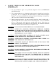
1. SAFETY RULES FOR OPERATING YOUR FIREPLACE Use only an Enerzone glass door, specifically designed for the model ENERZONE SOLUTION 2.5ZC. We recommend that our wood burning hearth products be installed and serviced by professionals who are certified in the United States by NFI (National Fireplace Institute®) or in Canada by WETT (Wood Energy Technical Training) or in Quebec by APC (Association des Professionnels du Chauffage).
WARNING: THE INFORMATION GIVEN ON THE CERTIFICATION LABEL AFFIXED TO THE APPLIANCE ALWAYS OVERRIDES THE INFORMATION PUBLISHED, IN ANY OTHER MEDIA (OWNER’S MANUAL, CATALOGUES, FLYERS, MAGAZINES AND/OR WEB SITES). PLEASE NOTE THAT THE PICTURES SHOWN IN THIS MANUAL ARE GENERIC AND MAY NOT MATCH EXACTLY THE LOOK OF YOUR FIREPLACE. REGISTER YOU WARRANTY ONLINE To receive full warranty coverage, you will need to show evidence of the date you purchased your unit. Keep your sales invoice.
2. THE FIREPLACE 2.1 INTRODUCTION The ENERZONE SOLUTION 2.5ZC fireplace is an energy efficient, heat circulating, close combustion fireplace. You will receive a lifetime of comfort and enjoyment from your fireplace provided it is installed, maintained and operated properly. Please read these instructions and retain this manual for future reference. Before beginning the fireplace installation, consult the local authorities to obtain your building permit and check your local building codes.
2.2 OPERATING THE ENERZONE SOLUTION 2.5ZC 2.2.1 Fuel The ENERZONE SOLUTION 2.5ZC is designed to work best when fuelled with seasoned cordwood. Use solid wood or processed solid fuel firelogs only. Hardwoods are preferred to softwoods since the energy content of wood is relative to its density. Hardwoods will result in a longer burning fire and less frequent refuelling. A moisture content of 15% to 20% (seasoned) is recommended.
2.2.3 First Fires The fresh paint on your fireplace needs to be cured to preserve its quality. Once the fuel load is properly ignited, only burn small fires in your fireplace for the first four hours of operation. Never open the air control more than necessary to achieve a medium burn rate. Make sure that there is enough air circulation while curing the stove. Open one or more windows. The odours can be smelled during the 3 or 4 first fires. 2.2.
desired temperature when, closing the primary air control, you can see a flame at the top of the firebox. The benefit of this technique will be cleaner glass, less creosoting, greater efficiency and the most pleasing fire for your enjoyment. In order to achieve an optimum efficiency from your unit, we suggest that you operate it with the air control completely closed. Make sure that you have a good fire going and an adequate ember bed before you completely close the air control.
2.2.7 Combustion Settings Accelerated Combustion The maximum heat output for the ENERZONE SOLUTION 2.5ZC is achieved by burning with the door closed and the combustion air opened. By this method, the ENERZONE SOLUTION 2.5ZC can produce up to 75,000 BTU of heat per hour. However, it will be necessary to reload with wood every one or two hours. This is the least efficient method of burning the ENERZONE SOLUTION 2.5ZC. Use caution when firing with the combustion air control wide open.
2.2.8 Smoking Causes and Troubleshooting To reduce the likelihood of smoking when opening the door, set the combustion air controls to the right (accelerated) before opening the door. Your fireplace has been designed and tested to provide smoke free operation. Occasionally, there may be a small amount of smoking upon lighting the fire, until the chimney heats up but this should not continue. If the fireplace continues to smoke it is probably for one of the following reasons: A.
IMPORTANT NOTES A. Do not block the hot air vents to the fireplace as this will cause the fireplace to overheat. B. Never start a fire using gasoline, kerosene, charcoal lighter fluid or any other combustible liquid. C. Do not burn coal. The sulphur in coal will corrode the firebox. D. Do not burn driftwood which has been in the ocean or salt water. The salt will corrode the firebox and chimney. E.
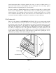
2.3.3 Fire Baffle Removal Prior to Cleaning the Chimney Before starting to clean your chimney, we recommend that you remove the fire baffle to avoid creosote dust collection on top of the baffle. Follow the steps below to remove the fire baffle: 1. Remove the front air tube by pulling out the cutter pin on the side of the tube. They are located at the top, underneath the baffle. 2. Lift the baffle and slide it out of the fireplace. You now have access to the chimney. Figure 2 2.3.
2.3.5 Plated Finish Maintenance Use a metal polish and a soft cloth to clean the plated finishes. Do not use abrasives such as steel wool, steel pads or an abrasive cleaner for they may scratch the finish. 2.3.6 Disposal of Ashes Do not attempt to clean the fireplace when the unit is hot. Ashes should be placed in a metal container with a tight fitting lid. The closed container of ashes should be placed on a noncombustible floor or on the ground, well away from combustible materials pending final disposal.
2.3.8 Glass Care – Replacement The two glasses used in the ENERZONE SOLUTION 2.5ZC are 5 mm thick and have the same dimension of 13.188" H x 11.875" W. They are tested to reach temperatures up to 1400º F. If a glass breaks, it must be replaced with one having the same specification. Contact your ENERZONE dealer to obtain a genuine replacement part (see “replacement parts”, in appendix to get the proper part number).
2.3.9 Glass Care – Cleaning The ENERZONE SOLUTION 2.5ZC is designed to keep the glass clean under normal operating conditions. If the ENERZONE SOLUTION 2.5ZC is operated continuously with the combustion air controls closed, the glass will tend to get dirty unless the fuel, firebox and glass are maintained at higher temperatures. To clean the glass, there are a number of specially designed cleaners. Your authorized ENERZONE dealer can recommend a suitable cleaner which is available in your area.
2.4 FIREPLACE INSTALLATION 2.4.1 Locating the ENERZONE SOLUTION 2.5ZC A. The best location to install your fireplace is determined by considering the location of windows, doors, and the traffic flow in the room where the fireplace is located, allowing space in front of the unit for the heart extension and the mantel, and taking into consideration the location of the hot air ducts (optional), outside air kit and chimney.
2.4.2 Heart Extension Requirements The hearth extension floor area must extend at least 16" (40 cm) in front of the hearth and at least 8" (20 cm) on each side of the door opening (see figure 7). The joint between the hearth extension and the fireplace hearth needs to be made of non-combustible material such as sheet metal (not included) as shown on figure 8.
When the fireplace is installed directly on the floor, a noncombustible floor protection in front of the unit must be installed and have an R value insulation equal to or greater than 1.00. The use of an R value is convenient when more than one material is going to be used in the hearth extension to cover the combustible surface. This is because R values are additive, whereas K values are not. To find the corresponding R factor to use for some selected materials, please see Appendix section.
2.4.2.2 How to eliminate the need of a R value It is however possible to eliminate the R value by elevating the unit from 4'' above the floor (see Figure 9), but the joint between the extension of the hearth and the fireplace must be protected by a non-combustible material. For example, a sheet metal (not included) as illustrated in Figure 9 (B). Please note that a combustible floor protection of at least 16” long must be installed in front of the fireplace as illustrated in Figure 9 (A).
2.4.3 Framing, Facing, Mantel, and Combustible Shelf Framing The construction of the framing, facing, and mantel must be in accordance with the standards and the following illustrations (figures 10 to 14): A. Frame the fireplace using 2" × 3" (5 cm x 8 cm) or heavier lumber. WARNING: COMBUSTIBLE FRAMING MATERIAL CANNOT BE USED IN THE SPACE DIRECTLY ABOVE THE FIREPLACE, EXCEPT FOR THE STUDS ABOVE THE FACING THAT SUPPORT THE FACING MATERIAL AND MANTEL.
Figure 10 Figure 11 19
Figure 12 Figure 13 20
Figure 14 21
INSULATED CHASE CONSTRUCTION Figure 15 Facing 1. Materials directly in contact with the faceplate of the fireplace, especially the vertical and horizontal surround, must be non-combustible and have the minimal dimensions as shown on figure 16. 2. Non-combustible materials such as brick, stone or ceramic tile may project in front of and onto the fireplace decorative frame. Caution: Materials must be installed so that the faceplate may be removed after the installation.
Figure 16 23
Combustible shelf To install any combustible shelf, refer to figure 17 for a safe installation. For example, a shelf with a 6’’ depth (152 mm) must be installed at least 50" (127 cm) above the base of the fireplace. Different shelf dimensions are listed in figure 17 in order to facilitate installation. However, the minimum depth of the shelf is 6" or less. If the depth of the shelf is not listed in the table, add 44’’ (112 cm) to the depth of your shelf to obtain the safe positioning of your shelf.
Figure 18 25
2.4.4 Blower connection The fan will come on as soon as the fireplace reaches its minimum start temperature. Have the wiring installed by a qualified electrician. Connect the wires from the power outlet to the terminal block, making sure that the white wire matches the white wire on the terminal. Connect the black wire with the black wire of the terminal block. The ground (green or skinned wire) must be attached to the fireplace metal frame.
2.5 HOT AIR DUCTING INSTALLATION Different hot air ducting systems can be installed with the ENERZONE SOLUTION 2.5ZC: Gravity kit Forced air kit 2.5.1 Gravity Kit The kit includes: 2 x hot air outlets (grilles and frames); 2 x 90o elbows with brackets; 1 deflector. The gravity kit allows you to block the upper fireplace louver. To do so, follow the steps below: a) Remove the upper louver from the fireplace; b) Install the deflector as shown on figure 20; c) Put the upper louver back into place.
The hot air grilles can be installed in the same room as the fireplace, or one or both of the grilles can be installed in adjacent or upper rooms. Installing the ducts at different elevations will tend to exhaust more heat out of the higher grilles (figure 23).
The duct system must be installed respecting the following: 1. Remove the plates closing up the 8" dia. holes on top of the fireplace. Then, cut the insulation in order to obtain two 8" dia. openings. Insert the ducting into each opening and fix it in place using the 6 steel brackets supplied (3 for each duct). 2. Maintain at least a 2" (50 mm) clearance between the ducts and the firestop; the required hole size for the hot air grilles (outlet) is 8¼" × 8¼" (210 mm × 210 mm). 3.
D) Attach a flexible pipe to the fan’s air outlet and route the flexible pipe to the chosen location. The ducting system can be installed either in an upper room or in a lower room; E) At that point, the flexible pipe can be attached to any air distribution grille. F) Make the electrical connections to the PC Board as explained with the forced air kit owner’s manual.
2.6 FRESH AIR KIT (OPTIONAL) During operation, the fireplace requires fresh air for combustion and draws air out of the house. It may starve other fuel burning appliances such as gas or oil furnaces. As well, exhaust fans may compete for air, causing negative pressure in the house, resulting in smoke entering the house from the fireplace. This situation is aggravated in modern airtight houses. To overcome this problem, we strongly recommend that you install fresh air kit (not included).
OUTSIDE AIR CONNECTION TO THE FIREPLACE FRESH AIR INTAKE ALUMINUM TAPE PLASTIC COVER OUTSIDE INTAKE FIRE PLACE CONNECTION FIREPLACE ALUMINUM TAPE 3" FLEXIBLE PIPE PLASTIC COVER FLEXIBLE PIPE SCREW OPENING FACING DOWN INSULATION ALUMINUM TAPE WALL ALUMINUM TAPE Figure 27 Figure 28 1) Remove the bottom louver 2) Seal the room air intake located on the right side by installing the plate over the opening.
3 OPTIONS 2.7 Figure 30 Figure 31 Figure 32 Figure 33 DOOR OVERLAY INSTALLATION In order to install the door overlay, simply put the overlay on the door frame. Then, pass the 4 bolts through the holes shown in figure 34. Finally, secure the door overlay in place using the 4 nuts. You will need to lift the gasket slightly. It is important that the gasket stays intact.
2.8 DOOR ALIGNMENT To adjust the door positioning and spacing, loosen the hinge screw and pivot the hinge until the door is in the correct position. To tilt the door, lock in place one of the two hinges and pivot the other. The door will tilt to one side or the other depending on the direction the hinge is pivoted. For the door to be straight, both hinges must be aligned along the same axis. If the door hinges are misaligned, it will tilt. It is therefore recommended to align them.
2.9 OPTIONAL FIRE SCREEN INSTALLATION (AC01308) Open the door. Hold the fire screen by the two handles and bring it close to the door opening. Lean the upper part of the fire screen against the top door opening making sure to insert the top fire screen bracket behind the primary air deflector as in (DETAIL A). Lift the fire screen upwards and push the bottom part towards the stove then let the fire screen rest on the bottom of the door opening.
3. THE CHIMNEY 3.1 CHIMNEY INSTALLATION NOTES 1. If possible, install an interior chimney as it will provide better performance. In areas with continuous temperatures below 18 C (0 F), the use of an exterior chimney increases the likelihood of operating problems such as low draught, high rate of creosoting, and poor start-up characteristics. Exterior chimneys are also prone to down-drafting and flow reversal.
3.2 CHIMNEY INSTALLATION INSTRUCTIONS 1. Cut and frame the holes in the ceiling, floor and roof where the chimney will pass and install rafter protectors (see figure 37). Use a plumb bob to line up the center of the holes. Make sure that the size of the floor and ceiling holes are in accordance with the chimney manufacturer’s instructions. Figure 37 2. From below, install a firestop supplied by the chimney manufacturer in each ceiling/floor separation through which the chimney will pass.
EXAMPLE OF TYPICAL CHIMNEY INSTALLATION Figure 38 38
When you build a combustible chase enclosure for chimney sections above the roof, refer to the chimney manufacturer for clearances to combustible materials.
3.3 OFFSET CHIMNEY INSTALLATION The minimum system height when using elbows is: Fireplace model ENERZONE SOLUTION 2.5ZC Chimney model All models Vertical installation 15 ft. (4.6 m) Two (2) elbows 15 ft. (4.6 m) Four (4) elbows 17 ft. (5.2 m) Table 1 After reaching the location requiring the elbow, proceed as follows: 1. Install the first elbow; turn it in the required direction. Secure it to the chimney according to the chimney manufacturer’s instructions.
Figure 40 Figure 41 41
TABLE 2 - LISTED CHIMNEYS FOR YOUR ENERZONE SOLUTION 2.5ZC CHIMNEY MANUFACTURER Selkirk Selkirk Selkirk Selkirk Selkirk Selkirk Selkirk Selkirk Selkirk Security Chimney Security Chimney Simpson Dura Vent Simpson Dura Vent Simpson Dura Vent ICC Metal Fab American Metal American Metal Olympia Chimney FMI (U.S.A.
TABLE 3 – LIST OF MANDATORY COMPONENTS CHIMNEY MANUFACTURER Selkirk MANDATORY COMPONENTS Ventilated roof flashing. Must have rafter protectors at the roof level if the chimney is enclosed at the attic level (see section 4). Rafter protector at the roof level if chimney is enclosed at the attic level (see section 4). Requires insulated attic radiation shield unless chimney is enclosed at the attic level. Requires the use of a 6AW7 (Solid pack 1") adapter for a ASHT+ of 7".
3.4 ANGLED WALL RADIATION SHIELD When passing through a combustible wall with the chimney at a 30 or 45 angle (30 or 45 in Canada and 30 only in the USA), an angled firestop or wall radiation shield provided by the chimney manufacturer must be installed. Only one is required. Follow the chimney manufacturer’s installation instructions. In cold climate locations, it is recommended that you use the insulated wall radiation shield since it will maintain the home’s thermal barrier.
3.5 CHIMNEY SUPPORT INSTALLATION Universal Roof Support This support has three possible uses: 1. It must be used on a roof to support the chimney. 2. It may be used on a floor, ceiling or roof above an offset to support the chimney above the offset. 3. It may be used on a floor, ceiling or roof as a supplementary support. For roof support installation, refer to the instructions provided with the support by the chimney manufacturer.
3.6 CHIMNEY CHASE AND MULTIPLE TERMINATIONS For the purpose of this manual, a chimney chase is considered a part of the chimney system rather than part of a building. The termination must be placed a minimum of 18" (460 mm) above the chase. For installations where more than one chimney is located in the same chase or within the same area, we suggest that their terminations be separated by at least 16" (410 mm) horizontally, and 18" (460 mm) vertically.
3.7 INSTALLATION INSTRUCTIONS FOR MASONRY APPLICATION WARNING: Before starting the installation, the masonry chimney must be inspected by a qualified sweep. The following requirements must be respected: 1. The chimney must be absolutely clear of any soot residue or creosote. Check for cracks, loose or missing bricks that could inhibit correct installation of the liner. 2. The clearance to combustible must be a minimum of 1" between the outside of the masonry and any wood framing or loose insulation. 3.
4. OPTIONS Gravity kit: Includes: one deflector, two 90o elbows, and two outlet grilles and frames, #AC01309 Central forced air kit: Includes: one blower, one 5" flex adapter, 3 pipe clamps, and one control box with heat sensor and PC Board. #AC01310 Outside air kit Includes: one 3" flex adapter, 2 pipe clamps, and one outside wall register #AC03500 Rigid fireguard Includes: one rigid fireguard #AC01308 Rafter protector Includes: one rafter protector kit* #AC03510 Part No.
5. APPENDIX 5.1 SPECIFICATIONS Weight: 385 lbs Height: 38" Width: 36.75" Depth: 26" Maximum recommended heating area: 500 to 2,100 square feet (with forced air kit) Heating capacity* – BTU/hr., EPA test wood: 30,500 Heating capacity* – BTU/hr.
5.4 THERMAL CHARACTERISTICS OF COMMON FLOOR PROTECTION MATERIALS* MATERIAL CONDUCTIVITY (k) PER INCH RESISTANCE (R) PER INCH THICKNESS Micore® 160 0.39 2.54 Micore® 300 0.49 2.06 Durock® 1.92 0.52 Hardibacker® 1.95 0.51 Hardibacker® 500 2.3 0.44 Wonderboard® 3.23 0.31 Cement mortar 5.00 0.2 Common brick 5.00 0.2 Face brick 9.00 0.11 14.3 – 20.00 0.07 – 0.05 Ceramic tile 12.5 0.008 Concrete 1.050 0.950 Mineral wool insulation 0.320 3.120 6.5 0.
Exploded view for replacement parts 51
List of replacement parts 1 1 1 2 3 4 5 6 7 8 9 10 11 12 13 14 15 16 17 18 19 20 21 22 23 24 25 26 27 28 29 30 31 32 33 34 35 36 37 38 39 40 41 42 43 44 45 46 47 48 49 50 51 52 53 53 53 AC01300 AC01301 AC01302 SE24150 SE45181 PL63866 30187 30185 30060 30556 44073 44091 44084 44087 44085 44046 30441 PL53141 AC02092 PL53139 PL53088 PL53150 AC06400 SE53076 30101 PL53035 AC06100 30114 24153 PL53100 SE24156 30569 30123 PL53101 30039 AC06100 SE24157 PL53089 PL53585 30124 21147 PL53144 22122 22123 AC03020 30068 P
ENERZONE LIMITED LIFETIME WARRANTY The warranty of the manufacturer extends only to the original consumer purchaser and is not transferable. This warranty covers brand new products only, which have not been altered, modified nor repaired since shipment from factory. Products covered under this warranty must have been manufactured after the revision date indicated below.