
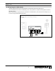
Specifications
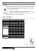

5
3000775 12.12
3. Mechanical Installation
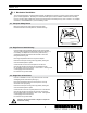
The code requirements for a mechanical draft system are different than those for a gravity venting system used with
gasoroil-redapplications.Generally,themechanicaldraftsystemmustbeinstalledaminimumof3feetaway
from any forced air inlet located within 10 feet and a minimum of 4 feet away from any door or window. For complete
information, consult ENERVEX or your local building codes.
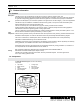
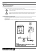
3.1 Transport Safety Device
Before mounting the fan make sure the transport safety
brackets have been removed (RSV315, 400 and 450 only).
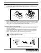
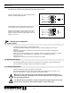
3.2 Single Fan on Steel Chimney
Insert the steel chimney adapter (SCA) into the chimney/stack.
The long collar engagement ensures safe anchoring (See Fig. 3).
If necessary, the adapter can be secured by means of long
self-tapping stainless steel screws into the side of the collar
through the chimney wall.
Place high-temperature silicone on top of the adapter.
Remove the transport securing device (if present) holding the
motor shaft and impeller in place.
Center the fan over the cutout and place on the silicone.
Open the fan housing and secure onto the adapter through
the pre-drilled holes in the bottom of each corner. Use lag bolts
or self-tapping sheet metal screws.
Do not block the (4) drain holes.
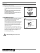
3.3 Single Fan on Roof Curb
If the fan is installed on a curb cap, secure the roof curb with
self-tapping sheet metal screws (see Fig. 4).
Place high-temperature silicone on the top of the curb cap
around the curb cap opening.
Remove the transport securing device (if present) holding the
motor shaft and impeller in place.
Center the fan on the curb cap and place the fan on the silicone.
Open the fan housing and secure onto the roof curb through
the pre-drilled holes in the bottom of each corner. Use lag bolts
or self-tapping sheet metal screws.
Do not block the (4) drain holes.
Fig. 4
Caution: Never place hands or ngers on top of fan
base when closing
Fig. 3
Fig. 2