
Specifications

10
3000775 12.12
5. Startup and Conguration
5.1 System Testing
• Checkthelinevoltagewiththemotornameplaterating.
• Checkthatthetransportsecuringdeviceholdingthemotorshaftandimpellerinplacehasbeen
removed.
• Determineiftheaxialvaneorimpellerisrunningfreeandhasnotbeensubjecttomisalignmentin
shipping or installation.
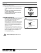
• Applypowerandcheckthattheaxialvaneorimpellerisrotatinginthedirectionofthearrowontheside
of the top motor cover (RSV400/450 only). All RSV fans run in a clockwise direction when
viewed from the top.
• Switchinganytwophasesinthejunctionboxwillreversetherotation.
5.2 Adjusting Fan Speed
• Startallheatingappliancesconnectedtothechimneywiththefaninstalled.Setthefanspeedcontrol
to the speed where no spillage is experienced anywhere in the system.
5.3 Testing Safety System
• AdjustthesettingoftheProvenDraftSystemorotherdevice.
• Starttheheatingappliancesandthechimneyfantomakesurethesafetydeviceisfunctioning.Turn
the fan off. After less than 1-2 minutes all appliances should be shut down.
Make sure the fan is running in the correct direction; the fact that the fan blows is no
guarantee it is doing so. Running the fan in the wrong direction over a longer period of
time will damage the motor.
It is important that the installation, start-up and system testing procedures are followed.
Failure to do so may have a major negative impact on motor expectancy.
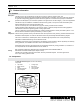
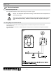
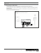
Fig. 11
The motor wiring terminals in Fig. 11 show default jumper
positions for 3x208-240VAC operation.
If the application requires 3x440-480VAC operation, the
jumper positions must be changed according to Fig. 12.
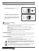
After wiring, make sure the motor is rotating in the proper
direction. This is marked on the motor end cover. If the
rotation is incorrect, swap the two wires going to the motor
terminals, U1 and W1.
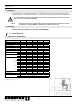
Fig. 12
RSV 400-450 can operate at either 3x208-230 VAC (default) or 3x440-480 VAC.