
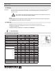
Specifications

8
3001391 06.14
4. Electrical Installation
4.1 Electrical Requirements
Power requirements depend on the fan size. They can be found on page 4.
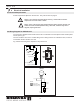
Danger: Turn off electrical power before servicing. Contact with live electric
components can cause shock or death.
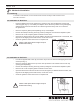
Notice: If any of the original wire supplied with the system must be replaced, use
similar wire of the same temperature rating. Otherwise, insulation may melt or
degrade, exposing bare wire.
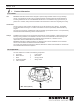
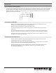
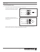
4.2 Wiring Diagram for GSV 250-315
The connection diagram below shows how the fan is connected to the fan speed control and the power
source (see Fig. 6).
Use a 2-conductor wire of min. 14 AWG with ground. Wiring must be run outside the duct, but can be
run between the duct and the roof curb.
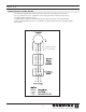
Fig.5showsthewiringofthecapacitorinthejunctionbox.
!
!
Variable Speed
Fan Motor
1 x 120 VAC, 60 Hz
Red
Black
White
LEGEND:
Factory Wired
Field Wiring (14AWG)
Connection (wire nut)
Neutral
Hot
Capacitor
Fan Motor
2-pole double-
throw switch
Fan speed
control
Fan *)
Junction box *)
F
an speed control *)
Repair switch
*) supplied by EXHAUSTO
To fan
To power
Black
Black
White
White
Red
Green
Fig. 4 Fig. 5
Fig. 6