
User guide


ENGLISH
11
• Remove circlips (24) reaction rollers
(25) and
roller pin (26).
• Clean all exposed components with a
mild solvent.
• Inspect all parts for damage.
• Dry all components. Apply a thin coat
of molybdenum disulphide lubricant
as indicated.
5.2.2 The hydraulic drive unit
• Check tightness of swivel
manifold
post retaining screws (see 5.3.2) and
gland.
• Pressurize the drive unit to maximum
pressure (Advance and Retract), and
check for any signs of leakage.
• Any damaged components or seals
must be replaced.
• Dry all components and apply a
thin coat of molybdenum disulphide
lubricant
as indicated.
5.3 Full maintenance
Note: Refer to the WCR4000 repair
parts sheet for detailed views of
components and subassemblies
referenced in sections 5.3.1 and 5.3.2.
5.3.1 The roller cassette
• Strip down and clean all exposed
components with a mild solvent.
• Drift out the
spring pin holding the
cylinder retaining pin, and remove
the
retaining pin
.
• Inspect all parts for damage.
•
Perform non destructive testing by
magnetic particle inspection on the
following components:
-
Sideplates
- Cylinder locating plate
- Cylinder retaining pin
- Reaction roller bracket and pin
- Reaction rollers and roller pin
• Dry all components. Apply a thin coat
of molybdenum disulphide lubricant
as indicated.
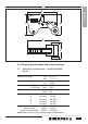
• Check retaining pin height (X) and fail
safe pin height (Y). Refer to Fig.P.
• Reverse the procedure to reassemble
the tool.
5.3.2 The hydraulic drive unit
• Remove the circlip from the
swivel
manifold block.
• Remove the hydraulic couplings.
• Remove the
swivel manifold block
from the drive unit.
• Remove
the retaining screws and the
swivel manifold post
.
• Remove all ‘O’ rings from swivel
manifold post.
• Carefully hold the cylinder body to
unscrew the cylinder gland.
• Hold the two flat sides of the piston
rod with a spanner. The rod is located
at the spigot.
• Remove the button head cap screw
from the piston.
• Remove the piston rod from the
cylinder spigot end.
• Remove the piston from the cylinder
gland end, using a suitable drift.
Retaining Pin Height - Dimension “X”
Metric Imperial
5,00 mm 0.197 inch
Fail Safe Pin Height - Dimension “Y”
Metric Imperial
3,00 mm 0.118 inch
Fig. P