
User Manual


6
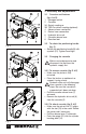
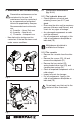
Fig. A
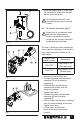
Fig. B
3 Assembly and adjustments
3.1 Overview and features
(fig. A or B)
1 Hexagon ratchet
2 Cassette
3A Swivel coupling or
3B TSP-Pro swivel coupling (optional)
4 Advance hose connection
5 Return hose connection
6 Hydraulic drive unit
7 Cassette release lever
8 Reaction foot
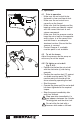
3.2 To attach the positioning handle
(fig. C)
• Secure the positioning handle (9) with
eye-bolt (10). Tighten hand tight.
3.3 Changing the cassette
Make sure to depressurize and
disconnect the tool from the
hydraulic supply first.
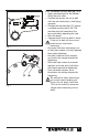
3.3.1 To remove cassette (fig. D & E)
• Make sure the piston is fully
retracted.
• Place the tool on a workbench or
support it using a hoist.
Hydraulic drive unit will disengage
from cassette in the following
steps. Be sure that cassette is
supported so it does not drop.
• Pull the cassette release lever (7)
outwards.
• Remove the hydraulic drive unit (6)
from the cassette (2).
3.3.2 To attach cassette (fig. D & E)
• Make sure the retract link (11) aligns
with the slot (13) in the crank. Rotate
the piston rod if necessary.
• Pull the release lever (7) outwards.
• Push the spigot (12) into the cylinder
locating plate (14).
Fig. C