
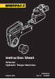
Owner's manual


6
ENGLISH
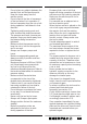
Fig. C
Fig. A
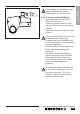
- Make sure to minimize torsional and
bending stresses in the tool, the hex
ratchet and any accessories.
- Do not strike the tool with a hammer
while under a full load. This will
invalidate the guarantee.
- Always observe the maintenance
instructions.
3 Assembly and adjustments
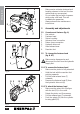
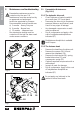
3.1 Overview and features (fig. A)
1 Hex ratchet
2 Fastener head
3 Swivel coupling
4 Advance hose connection
5 Return hose connection
6 Hydraulic drive unit
7 Head release lever
8 Reaction foot
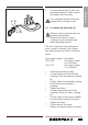
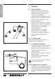
3.2 To change the fastener head
(fig. B & C)
Make sure to depressurize and
disconnect the tool from the hydraulic
supply first.
3.2.1 To remove the fastener head
• Make sure the piston is fully retracted.
• Hold the tool with the reaction foot
pointing upwards.
• Pull the head release lever (7)
outwards.
• Remove the fastener head (2) from
the hydraulic drive unit (6).
3.2.2 To attach the fastener head
• Make sure the retract link (9) aligns
with the slot (11) in the crank.
Rotate the piston rod if necessary.
• Pull the release lever (7) outwards.
• Push the spigot (10) into the cylinder
locating plate (12).
7
6
2
3 4
2
1
5
6
78
92
1211
10
6
Fig. B