
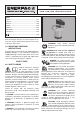
Owner's manual

7
J
63
J2
0.004
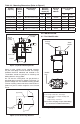
Manifold
O-Rings
(included)
Mounting Bolts
(included)
0,5mm x 45º
ø 4,8mm
ø D3
Mtg. Hole
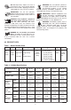
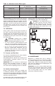
Figure 1, Cylinder Mounting Details
Before a swing cylinder can be manifold mounted,
the port screw plugs must be removed. The O-Rings
provided should be lubricated and installed in the
counter-bore around the port prior to mounting and
bolting down the swing cylinder.
Be sure that the O-Ring does not get pinched or
damaged during mounting as leakage could result. To
prevent leakage from the manifold mounting, provide
a fixture mounting surface with latness within 0,08 mm
[0.003 inch] and a surface roughness not to exceed
Ra 1,6.
Port Screw Plug
(remove)
O-Ring
Upper Flange
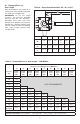
Figure 2, Port Screw Plug Removal
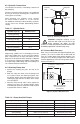
6.0 INSTALLATION
6.1 Port Identification
KEY:
A Port: Plunger rotates 90 ° and clamps
B Port: Double-acting -- Plunger unclamps and
rotates -90 °
Single-acting -- Vent Port
Do not remove vent plug except to attach tubing.
(see Section 6.3 for additional information)
SIDE VIEW
BOTTOM VIEW
Manifold
Ports
“Unclamp”
Position
“Clamp”
Position
Figure 3, Cylinder Port Locations
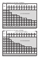
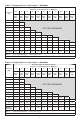
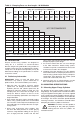
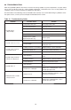
Table 10 - Mounting Dimensions (Refer to Figure 1)
Cylinder
Capacity
Fixture
Thread
Ø D3
mm
Mounting Bolt
Thread (J)
Minimum
Mounting
Depth (J2)
Manifold
O-ring
ARP No.
Lubricated Bolt
Torque
mm inch Nm ft-lbs
2,0 kN [441 lbs] 44,5 M5 x 0,8 x 30 mm long 10
0.39
568-010 8,0-9,0 5.9-6.6
3,5 kN [769 lbs] 50,5 M5 x 0,8 x 30 mm long 11
0.43
568-010 8,0-9,0 5.9-6.6
5,0 kN [1111 lbs] 55,5 M6 x 1,0 x 30 mm long 12 0.47 568-011 13,5-15,0 10.0-11.0
7,0 kN [1570 lbs] 65,5 M6 x 1,0 x 30 mm long 15
0.59
568-011 13,5-15,0 10.0-28.0
9,0 kN [2019 lbs] 88,5 M8 x 1,25 x 30 mm long 15
0.59
568-011 32,0-38,0 23.6-28.0
20,0 kN [4490 lbs] 90,5 M10 x 1,5 x 35 mm long 20 0.79 568-011 47,9-53,1 65.0-72.0
Note: O-rings and mounting bolts included with cylinder.