
Owner's manual

11
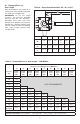
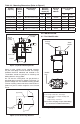
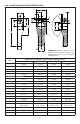
10.0 CLAMP ARM MACHINING SPECIFICATIONS
F
G
K
M
N
R
C
J
L
2.3
125
115
S
T
50
40
V
U
A
H
B
E
D
P
Q
Item
Dimensions in millimeters [inches] unless otherwise noted
2,0 kN 3,5 kN and 5,0 kN 7,0 kN and 9,0 kN 20,0 kN
A 25 [0.99] 27 [1.06] 30 [1.18] 38 [1.49]
B (Max.) 150 [5.90] 190 [7.48] 190 [7.48] 210 [8.26]
C 30 [1.18] 34 [1.34] 40 [1.57] 48 [1.89]
D 16 [0.63] 16 [0.63] 18 [0.70] 21 [0.82]
E 19,5 [0.77] 20 [0.79] 22 [0.87] 26 [1.02]
F (3 places) 67 [0.26] 84 [3.30] 86 [3.39] 100 [3.94]
G 29 [1.14] 31 [1.22] 34 [1.34] 40 [1.58]
H 12,5 [0.49] 13,5 [0.53] 15 [0.59] 19 [0.74]
J 15 [0.59] 17 [0.67] 20 [0.79] 24 [0.94]
K (Dia.) ø 13,5 [0.53] ø 13,5 [0.53] ø 16,5 [0.65] ø 18,5 [0.73]
L 9 [0.35] 11 [0.43] 11 [0.43] 13 [0.51]
M (Dia.) ø 8,5 [0.33] ø 8,5 [0.33] ø 10,5 [0.41] ø 12,5 [0.49]
N (thread) M8 x 1,25 M8 x 1,25 M10 x 1,5 M12 x 1,25
P 6 [0.23] 8 [0.31] 9 [0.35] 12,75 [0.50]
Q 12 [0.47] 16 [0.63] 18 [0.71] 25,5 [1.00]
R (2 places) 21º - 23º 21º - 23º 21º - 23º 21º - 23º
S (Dia.) ø 22,75 - 23,00
[0.895 - 0.905]
ø 24,75 - 25,00
[0.974 - 0.984]
ø 27,75 - 28,00
[1.092 - 1.102]
ø 35,50 - 36,00
[1.397 - 1.417]
T (Dia.) ø 20 H8 ø 22 H8 ø 25 H8 ø 32 H8
U 3,8 - 4,3 [0.15 - 0.17] 3,8 - 4,3 [0.15 - 0.17] 3,8 - 4,3 [0.15 - 0.17] 4,7 - 5,3 [0.19 - 0.21]
V 1,0 - 2,0 [0.04 - 0.09] 1,0 - 2,0 [0.04 - 0.09] 1,0 - 2,0 [0.04 - 0.09] 1,0 - 2,0 [0.04 - 0.09]
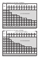
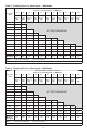
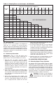
IMPORTANT: Refer to Section 3.1 to
determine the maximum clamp arm
length and pressure for the desired
clamping force.
3 PLACES
2 PLACES