
User Manual
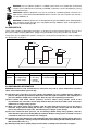
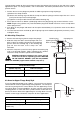
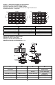
Before a swing cylinder can be manifold mounted, the port screw plugs and
copper gaskets must be removed.
The o-rings provided should be lubricated and installed in the counter-
bore around the port prior to mounting and bolting down the swing
cylinder.
Be sure that the o-ring does not get pinched or damaged during
mounting as leakage could result. To prevent leakage from the
manifold mounting, provide a fixture mounting surface with
flatness within 0,08 mm (0.003 in.) and a surface roughness not
to exceed Ra 1,6.
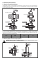
6.0 INSTALLATION
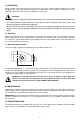
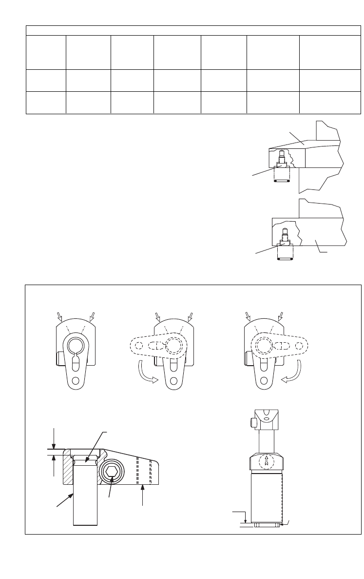
These Swing Cylinders are designed so that you can set the
position of the clamp arm after mounting the cylinder. If you need
to change the rotation direction, do it before mounting the
cylinder.
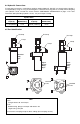
6.1 Changing Plunger Rotation (if needed)
5
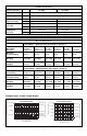
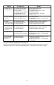
Manifold Specifications
Cylinder Max. Oil Fixture Mounting Minimum Lubricated Manifold
Capacity Channel Hole Threads Thread Mounting O-Ring
Diameter Diameter Depth Bolt Torque Dimensions
Ø A Ø B C D I.D. x w
2,2 kN 4 mm 1.15 ± .03 M5 12 mm 4,5-5,4 Nm 6,07 x 1,78 mm
500 lb 0.156" 0.473" 40-48 in-lbs 0.239 x 0.070"
5,6 kN 4 mm 1.42 ± .03 M6 15 mm 12,2-14,9 Nm 7,65 x 1,78 mm
1250 lb 0.156" 0.591" 9-11 ft-lbs 0.301 x 0.070"
A
B
S
L
R
A
B
R
S
L
A
B
L
R
S
.25 "
(6,4mm)
6,4 mm
(0.25")
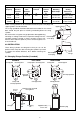
Clamp position
Unclamp port
Unclamp position
Clamp port
Clamp position
Clamp and
unclamp position
Unclamp
position
Unclamp portClamp port
Unclamp portClamp port
Retaining ring removed
from groove.
Plunger
Clamp
arm
bolt
Clamping
arm
Approximately
4 turns out.
Bottom plug
STRAIGHT LEFT SWING RIGHT SWING
Upper Flange
Remove port
screw plug.
O-ring
O-ring
Lower
Flange
Remove port
screw plug.