
Manual
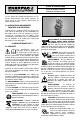

5.0 MOUNTING SPECIFICATIONS
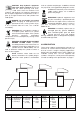
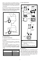
5.1 Mounting Threaded Body Cylinders
Threaded body cylinders can be threaded into a tapped
hole, secured to the fixture using a mounting flange,
threaded into the fixture and secured with a jam nut, or
mounted through a clearance hole and secured with jam
nuts. See illustrations below.
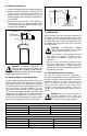
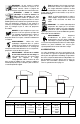
When a threaded body style swing cylinder is being
installed in a fixture, the thread engagement should be
no less than the thread engagement for the standard
Enerpac mounting flange. If a cylinder is being mounted
using just the lower portion of the threads, the
engagement should be increased for additional support.
See table below for minimum thread engagement.
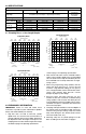
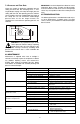
5..2 Mounting Upper and Lower Flange Cylinders
WARNING: The fixture must be capable of
withstanding 350 bar (5,000 psi) hydraulic
working pressure when the cylinders are
manifold mounted.
Cylinder Capacity Minimum Thread
Engagement
9,0 kN (2024 lb) 16 mm (0.63")
18,8 kN (3900 lb) 25 mm (1.00")
35,0 kN (7600 lb) 30 mm (1.25")
4
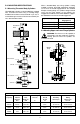
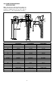
Manifold Specifications
Cylinder Max. Oil Fixture Mounting Minimum Lubricated Manifold
Capacity Channel Hole Threads Thread Mounting O-Ring
Diameter Diameter Depth Bolt Torque Dimensions
Ø A Ø B C D I.D. x w
9,0 kN 4mm 49,1± 0,8 M6x30 15 mm 13,5-15 Nm 4,34 x 3,56mm
2024 lb 0.156" 1.93± .03 0.59" 10-11 ft-lbs 0.171 x 0.139"
18,8 kN 0.156" 63,4± 0,4 M8x30 15 mm 32-38 Nm 4,34 x 3,56mm
3900 lb 4 mm 2.50 ± .02 0.59" 25-30 ft-lbs 0.171 x 0.139"
★ 35,0 kN 0.156" 77,5± 0,3 M10x30 15 mm 65-72 Nm 4,34 x 3,56mm
7600 lb 4mm 3.05 ± .01 0.59" 48-53 ft-lbs 0.171 x 0.139"
★ includes. long stroke
Threaded into
fixture
Mounting
flange
Oil connection
Jam nut
Jam nuts
Oil connection
Manifold
O-ring
Manifold
O-ring
0.003
0.003
A
B
C
D
A
C
D