
Manual

4.0 SPECIFICATIONS
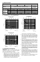
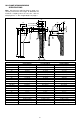
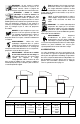
4.1 Clamping Force -v- Arm Length Graphs
4.2 PRELIMINARY INFORMATION
IMPORTANT: Failure to read and follow these
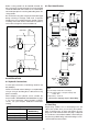
instructions may lead to system malfunction or product
failure, and could invalidate your warranty.
1. High flow rates can lead to excessive cylinder
speed which can cause the kick-out mechanism to
activate. Hydraulic pressure and cylinder speed must
be adjusted to match the length of clamp arm. The
clamping force also varies with the length of the clamp
arm.Refer to page 2 for operating specifications.
Refer to page 2 for operating specifications.
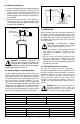
2. Flow controls with return checks should be used to
reduce swing cylinder speed to the recommended
rate. The return checks help minimize back pressure
that could lead to an unclamp malfunction on single-
acting systems.
3. When using single-acting swing cylinders, limit the
return flow back pressure to 3,5 bar (50 psi)
maximum. Large diameter tubing (10 mm [3/8 in.]
O.D. or larger) and flow controls with free flow return
checks help minimize back pressure. Consult
Enerpac for proper system design.
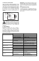
4. Excessive return flow back pressure can also
activate the kick-out mechanism on double-acting
swing cylinders. Limit the return flow back pressure
to 42 bar (600 psi) maximum. Double-acting systems
should be set up for a metered-in with reverse free
flow in the clamp port.
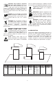
5. Clamping of the part should occur at the midpoint of
the vertical travel. No clamping of part shall occur
while the swing clamp is turning. Clamp arm should
freely travel during the 90° rotation (avoid contact
with cutter heads, tools, etc.).
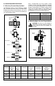
6. Attaching clamp arm to cylinder plunger must be
done according to the instructions on page 6.
(110)
(220)
(340)
(450)
(560)
350 200 160 135 115 100
68 90 110 130 150 165
Pressure bar (psi)
Force kN (lbs.)
CAS-352 CAL-352Length mm (in.)
4,0 l/min . . . . . . . . . . . . . . . Q . . . . . . . . . . . . . . . . 2,0 l/min
(240 in
3
/min )
(5000) (2900) (2320) (1960) (1770) (1450)
0
5
10
15
20
25
(2.68) (3.55) (4.33) (5.12) (5.90) (6.50)
35,0 kN (7600 lb) Models
(120 in
3
/min)
(670)
30
(780)
35
(670)
30
(60)
(110)
(170)
(220)
(280)
(340)
350 250 215 175 150 130 120
55 70 90 110 130 150 165
Pressure bar (psi)
Force kN (lbs.)
CAS-202 CAL-202Length mm (in.)
2,5 l/min . . . . . . . . . . . . . Q . . . . . . . . . . . . . . 1,5 l/min
(150 in
3
/min)
(5000) (3630) (3120) (2540) (2200) (1890) (1740)
0
2,5
5,0
7,5
10,0
12,5
15,0
(2.17) (2.76) (3.55) (4.33) (5.12) (5.90) (6.50)
18,8 kN (3900 lb) Models
(92 in
3
/min)
(390)
17,5
(450)
20,0
(45)
(90)
(130)
(180)
(220)
(270)
350 265 200 160 135 115 100
45 60 80 100 120 140 160
Pressure bar (psi)
Force kN (lbs.)
CAS-92 CAL-92Length mm (in. )
1,0 l/min . . . . . . . . . . . . . Q . . . . . . . . . . . . . . 0,6 l/min
(61 in
3
/min )
(5000) (3840) (2900) (2320) (1960) (1770) (1450)
0
2
4
6
8
10
12
(1.77) (2.36) (3.15) (3.94) (4.73) (5.51) (6.30)
9,0 kN (2024 lb) Models
(37 in
3
/min )
3
Cylinder Specifications
Capacity kN (lbs) 9,0 kN (2024) 18,8 (3900) 35,0 (7600) 35,0 (7600)
Long Stroke
Body Style threaded body, lower flange, or upper flange mounting
upper flange
mounting
Cylinder Type single-acting and double-acting double-acting
Hydraulic clamp 12 (0.47) 14,0 (0.55) 16,0 (0.63) 31,8 (1.25)
Stroke [mm (in)] total 22 (0.87) 28,0 (1.10) 30,0 (1.18) 46,5 (1.83)
Effective Area clamp 3,13 (0.49) 7,16 (1.11) 12,42 (1.925) 12,42(1.925)
[cm
2
(in
2
)] unclamp 8,04 (1.25) 15,21 (2.356) 23,76 (3.683) 23,76(3.683)
Oil Capacity clamp 6,88 (0.42) 20,0 (1.22) 37,2 (2.27) 57,9 (3.53)
[cm
3
(in
3
)] unclamp 17,69 (1.08) 42,6 (2.60) 71,3 (4.35) 111,0 (6.77)