
Manual
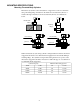

Mounting Upper and Lower Flange Cylinders
A WARNING
The fixture must be capable of withstanding 5,000 psi (350 bar) hydraulic
working pressure when the cylinders are manifold mounted.
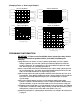
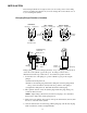
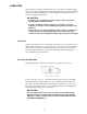
Before a swing cylinder can be manifold
mounted, the port screw plugs and copper
gaskets must be removed.
The o-rings provided should be
lubricated and installed in the
counter-bore around the port prior to
mounting and bolting down the swing
cylinder.
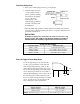
Be sure that the o-ring does not get
pinched or damaged during mounting as
leakage could result. To prevent leakage
from the manifold mounting, provide a
fixture mounting surface with flatness
within 0.003 in (0,08 mm) and a surface
roughness not to exceed 32√ rms.
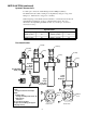
0.003
A
B
C
D
Manifold
O-ring
0.003
A
C
D
Manifold
O-ring
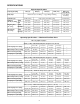
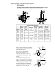
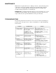
Manifold Specifications
Cylinder
Capacity
Max. Oil
Channel
Diameter
Ø A
Fixture
Hole
Diameter
Ø B
Mounting
Threads
C
Minimum
Thread
Depth
D
Lubricated
Mounting
Bolt Torque
Manifold
O-Ring
Dimensions
I.D. x w
300 lb
1kN
0.156"
4 mm
1.05 ± .03 8-36 UNF 0.50"
13 mm
29-35 in-lbs
3,3-4,0 Nm
0.239 x 0.070
6,07 x 1,78 mm
500 lb
2,2 kN
0.156"
4mm
1.15 ± .03 10-32 UNF 0.63"
16 mm
40-48 in-lbs
4,5-5,4 Nm
0.239 x 0.070"
6,07 x 1,78 mm
1250 lb
5,6 kN
0.156"
4 mm
1.42 ± .03 25-28 UNF 0.75"
19 mm
9-11 ft-lbs
12,2-14,9 Nm
0.301 x 0.070"
7,65 x 1,78 mm
2600 lb
11,6 kN
incl.
long stroke
0.156"
4 mm
1.93 ± .03 .3125-24
UNF
0.88"
22 mm
18-22 ft-lbs
24,4-29,8 Nm
.301 x .070
7,65 x 1,78 mm
Remove port
screw plug.
o-ring
Lower
Flange
Remove port
screw plug.
o-ring
Upper Flange
5