
Manual

11
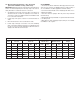
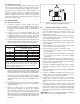
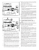
Table 2, Technical Data, Enerpac GT Series Hydraulic Tensioners
Series
Maximum
Pressure
Max Load
Hydraulic
Effective Area
Maximum Stroke Weight
psi bar
lbf klbf kN inch
2
mm
2
inch mm lbs. Kg
GT1 21,750 1500 50,414 50,4 224 2.32 1496 0.39 10,0 9.7-11.1 4,2-4,8
GT2 21,750 1500 90,256 90,2 402 4.15 2677 0.39 10,0 14.5-23.1 6,3-7,0
GT3 21,750 1500 172,847 172,8 769 7.95 5127 0.39 10,0 26.3-29.9 11,4-13,0
GT4 21,750 1500 329,780 329,7 1467 15.16 9782 0.39 10,0 47.2-53.4 20,5-23,2
GT5 21,750 1500 508,374 508,3 2262 23.37 15079 0.39 10,0 73.9-84.5 32,1-36,7
GT6 21,750 1500 639,598 639,5 2846 29.41 18972 0.39 10,0 103.1-115.7 44,8-50,3
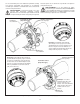
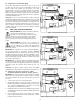
7.4 De-tensioning Instructions - 50% Coverage
(tensioner installed on every other stud)
IMPORTANT: Read precautions and instructions at beginning of
Section 7.0 before beginning the following steps. Also refer to
safety information contained in sections 2.1 and 2.2.
1. Assemble the tensioner(s) to the fi rst 50% of stud(s) to be
de-tensioned and connect the hydraulic hoses. Refer to
sections 6.1 and 6.2 for additional tensioner installation and
hose connection instructions.
2. Follow steps 2 through 8 of Section 7.3 for the fi rst 50% of
studs.
3. Move the tensioners to the second 50% of studs.
4. Follow steps 2 through 9 of Section 7.3 for the remaining
50% of studs. Note that the “break loose” hydraulic pressure
for the second set of studs will likely be about the same or
slightly lower than that for the fi rst set.
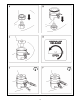
8.0 STORAGE
The tensioner’s black oxide fi nish will help protect it from rust
and corrosion. However, for added protection, a light coating of
oil or rust inhibitor should be applied to all metal surfaces.
Cover the internal threads of the threaded puller with oil or a
suitable rust inhibitor.
Store the tensioner upright, with the piston fully retracted
inside the body.
Always keep dust caps installed on couplers when the tensioner
is not being used.
Wipe all hoses clean and apply a light coating of oil or suitable
rust inhibitor to all couplers.
•
•
•
•
•