Installation & Operating Manual 3002503 11.06 RSIB 300-500 Power Venter USA CAN Product Information........................ Chapters 1 + 2 Mechanical Installation ......................... Chapter 3 Electrical Installation ............................. Chapter 4 Start Up and Configuration .................. Chapter 5 Maintenance and Troubleshooting ...... Chapter 6 ERTEK INT Job Name: CM C LISTED Installer: US Installation Date: READ AND SAVE THESE INSTRUCTIONS! EXHAUSTO Inc.
3002503 11.06 1. Product Information 1.1 1.2 1.3 1.4 2. Specifications 2.1 Dimensions & Capacities.......................................................................5 3. Mechanical Installation 3.1 3.2 3.3 3.4 3.5 Function................................................................................................3 Components..........................................................................................3 Shipping.........................................
002503 11.06 1. Product Information 1.1 Function Use The EXHAUSTO RSIB Power Venter is intended for use as an in-line draft inducer/power venter. It can be installed in-line with the chimney or stack, and can be used in sidewall and vertical venting arrangements. It is specifically designed for applications requirinng efficient operation, low noise level, low energy consumption, variable speed and compact design.
3002503 11.06 1.3 Shipping Standard packing list The RSIB contains the following: • The RSIB is shipped with two integrated sets of mounting brackets for use when hung from the ceiling. If other components are shipped, these will appear as separate items on the shipping packing list. 1.4 Warranty Complete warranty conditions are available from EXHAUSTO, Inc.
3002503 11.06 2. Specifications 2.1 Dimensions & Capacities Model RSIB 300 Fan Type Motor Type Amperage VAC 1 x 120 Amps 5.8 RSIB 500 3 x 200-240 / 3 x 440-480 3.6 / 1.7 6.5 /2.9 9.0 / 4.0 Output HP 0.5 1.0 2.0 3.0 kW 0.35 0.75 1.5 2.2 RPM 1600 Duct Connection (Nominal) Dimensions RSIB 400 TEFC (Class H) Voltage Motor RSIB 350 Centrifugal Impeller (B-wheel) in 1740 14 16 20 mm 300 350 400 500 in 19.9 16.9 21.9 22.2 mm 506 430 557 564 in 4.8 5.6 6.5 6.
3002503 11.06 3. Mechanical Installation 3.1 General Warning: Failure to install, maintain and/or operate the RSIB Power Venter in accordance with the manufacturer’s instructions may result in conditions which can produce bodily injury and property damage. The RSIB must be installed by a qualified installer in accordance with these instructions and all local codes, or in their absence, with the latest edition of The National Fuel Gas Code (NFPA54/ANSI223.1), NFPA 211, NFPA 31 or Canada CAN/CSA-B149.
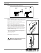
3002503 11.06 The figure below shows typical installation arrangements: Fig. 3 Vertical Venting Sidewall Venting 3.3 Mounting of Power Venter The power venter can be installed in a variety of positions. It can be suspended from a ceiling or placed on a shelf/floor. Placement on a shelf requires special hardware and vibration dampers. Fig. 4 Threaded rod Suspension from a ceiling does not require any special hardware other than threaded rods, nuts, and hangers. Follow Fig. 4 and 5.
3002503 11.06 3.4 Connection to Chimney or Vent Follow the recommendations by the vent or stack manufacturer. For optimal performance, the distances in Fig. 6 should be observed. Fig. 6 3xD D 3xD D 3.5 Connection to Flexible Duct Flexible duct (FLF) is used to reduce the effects of pulsating appliances on the fan and duct system. If used, the FLF should be connected between the fan inlet/ outlet and the main vent or stack as shown in Fig. 7.
3002503 11.06 4. Electrical Installation 4.1 General Danger: Turn off electrical power before servicing. Contact with live electric components can cause shock or death. ! Notice: If any of the original wire supplied with the system must be replaced, use similar wire of the same temperature rating. Otherwise, insulation may melt or degrade, exposing bare wire. All wiring must be in compliance with the local codes or in their absence, the National Electric Code, NFPA70.
3002503 11.06 4.3 Wiring Diagram – RSIB 350-500 Power Venter and motor specifications can be found under “Sec. 2.1 Dimensions and Capacities”. The power venter is equipped with a variable speed motor. Fig. 9 below shows a typical wiring diagram utilizing a Variable Frequency Drive (adjusting the speed is possible). If it is not a requirement that the speed can be adjusted, a motor starter should be installed in lieu of the VFD, if required by local codes. Fig.
3002503 11.06 4.4 Installing a Proven Draft Switch A safety system must be interlocked with the appliance. The safety system could utilize a Proven Draft Switch (PDS-1), a thermal switch, a flow switch or a sail switch. The device must be interlocked with the heating appliance(s) so it shuts down in case of insufficient draft, fan failure or power failure. Please refer to the PDS Installation Manual for wiring instructions.
3002503 11.06 4.6 Checking and Changing Rotation of RSIB 350, 400, and 500 For a more precise determination, you may also see down inside the fan housing, as shown in Fig.13. The arrow shown (not actually inside fan housing) shows the proper rotation. It is possible for the fan to operate with improper rotation. However, although some performance can be seen the fan will probably only provide 25-30% of full capacity.
3002503 11.06 5. Startup and Configuration 5.1 General The purpose of this fan is to ensure safe venting for a single appliance or multiple appliances. This can be performed via modulation, or through a single speed where modulation is not required. This is accomplished by starting a chimney fan/power venter when the appliance calls for heat, and stopping the fan when the heat demand has been satisfied. 5.2 System Testing 1. 2. 3. 4. 5.
3002503 11.06 6. Maintenance and Troubleshooting 6.1 General The power venter is designed for prolonged use, and no regular maintenance is required. It should be inspected periodically (at least once a year), and cleaned, if needed. This specifically applies in case it is being used with fuel oil. The power venter is designed to make this an easy task. The front part of the venter has the motor and impeller mounted on it, and it slides out to provide easy access. 6.
3002503 11.06 6.3 Troubleshooting Problem Possible Cause Solution The fan is not operating - No power to the fan - Check the power supply wires in the junction box by the fan. - Check the circuit breaker. - Check that the fan is actually turned on. The fan is not running at full speed and/or is humming - The capacitor is improperly connected or not connected at all (RSIB 300 only) - Check the connections inside the junction box. The capacitor must be installed according to the wiring diagram.
3002503 11.06 RSIBEBC 300,12, 350, EBC400, 14 500 EN60335-1, DS/EN 292-1, DS/EN DS/EN 292-2 EN 60 335-1, EN 60 335-2-80,EN60335-2-80, DS/EN ISO 12100-1:2003, ISO 12100-2:2003 98/37/EF/-EEC/-EWG/-CEE 98/37/EF/-EEC/-EWG/-CEE Langeskov, 01.03.2005 EXHAUSTO Inc. 1200 Northmeadow Pkwy. Suite 180 Roswell, GA 30076 P: 770.587.3238 F: 770.587.4731 T: 800.255.2923 info@exhausto.com us.exhausto.