
User Guide


035-18496-000-C-1102
8 UnitaryProductsGroup
MOTOR MOUNT ARRANGEMENTS
The motor mounting arrangement can be changed to allow
motor access based on the airflow arrangement required.
The recommended motor location for each blower arrange-
ment is as follows.
LA300/LB360/LB480 MOTOR ARRANGEMENTS
The LA300, LB360 and LB480 units are shipped with the
motor mount in location A as shown in 4. If this is the desired
position, the motor mounting assembly is already in the cor-
rect position and the motor and drive package can be
installed without modifications.
ADDITIONAL MOTOR ARRANGMENTS FOR LA300/
LB360/LB480
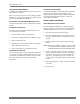
Move the entire motor amounting assembly (both the mount-
ing plate and the channels) so that the mounting plate will be
in the correct location.
1. Rotate the motor mounting plate 180 degrees on the
mounting channels. (For locations B, and D only! Do not
rotate the plate for location C or E.)
2. Install the motor and drive package.
NOTE: The blower section must be lifted off the evap-
orator section to gain access to the mounting
channel fasteners. Since these sections have
to be repositioned for the arrangements 2
through 10 and 12 of 6, the motor mounting
assembly should be relocated before the two
sections are rejoined.
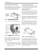
FIGURE 4 - LA300/LB360/LB480 MOTOR
LOCATION A
MOTOR
MOTOR
MOUNTING
CHANNELS
MOTOR
MOUNTING
PLATE
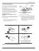
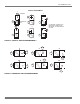
FIGURE 5 - LA300/LB360/LB480 MOTOR ARRANGEMENTS
SEE
NOTES
ARRANGEMENT 1, 4, 8 OR 11
A
B
SEE
NOTES
SEE
NOTES
C
D
C
E
SEE
NOTES
ARRANGEMENT 3, 5 OR 10
ARRANGEMENT 9 OR 12
ARRANGEMENT 2, 6 OR 7
NOTE: Since the motor mounting assembly cannot be
secured to the panel with the blower openings,
the motor cannot be installed in either of the
normally recommended bottom positions.