
User Guide


035-18496-000-C-1102
Unitary Products Group 13
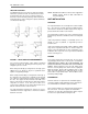
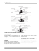
FIGURE 9 - DETAILS FOR SECURING BOTTOM MOUNTING SUPPORTS
3
NOTE: The following illustration shows how the channels
should be secured to the unit using the hardware
provided with the suspension accessory.
(2) 9/16 HOLES FOR 1/2
HANGER RODS
SUSPENSION
CHANNEL
5/16 NUT,
LOCKWASHER,
FLATWASHER
UNIT PANEL
5/16 BOLT,
FLAT-WASHER
UNIT ANGLE
SIDE
PANEL
5/16 NUT,
FLATWASHER
3/8 NUT (USED
AS SPACER)
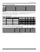
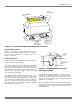
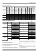
FIGURE 10 - LA300/LB480/LB360 WEIGHT DISTRIBUTION
AX
3
1-1/2
EVAP. C OIL
S E C TIO N
BLOWER
S E C TIO N
HOR IZONTAL
LE U360 O R 480
UNIT S US PE NDE D
FR OM ABOVE
HE AT ING C OIL
2
SUSPENSION
ANGLE S
1
BLOWER
S E C TIO N
EVAP.
COIL
S E C TIO N
CX
1
2
3
3
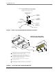
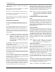
The s ame c hannels c an be us ed in e ither position. W hen used to
support at vertical unit, th es e c hannels s hould be cut to match the
bottom dimens ion of the e vaporator c oil s ection.
The s us pension c hannels have two s ets of mounting holes to
accommodate horizontal units with or without a heating c oil. O n
a horizontal unit without a heating coil, th e s uspension c hannels
will e xtend 3" beyond both e nds of the unit.
The s ame c hannels c an be us ed to s upport a horizontal, fl oor-
mounted unit from below.
4
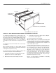
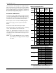
After thes e bottom c hannels a re c ut per N ote 1 , a new h ole will have
to be drilled a t the cut end if the unit is to be mounted on isolators.
4
VERTICAL LA300, LB360, LB480
UNIT SUPPORTED FROM BELOW
D
B
C
A
D
C
B
A
AX
BX
BX
BX
BX