INSTALLATION MANUAL CONTENTS GENERAL . . . . . . . . . . . . . . . . . . . . . . . . . . . . . . . . . . . . 4 REPLACEMENT PARTS . . . . . . . . . . . . . . . . . . . . . . . . 4 SPLIT-SYSTEM (AIR COOLED) EVAPORATOR BLOWER MODELS: LB300 LB360 LB480 LB600 INSPECTION. . . . . . . . . . . . . . . . . . . . . . . . . . . . . . . . . . 4 INDOOR PRODUCT NOMENCLATURE . . . . . . . . . . . . 5 UNIT INSTALLATION. . . . . . . . . . . . . . . . . . . . . . . . . . 11 MAINTENANCE . . . . . . . . . . . . . . . . . . .
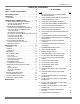
035-18496-000-C-1102 TABLE OF CONTENTS GENERAL . . . . . . . . . . . . . . . . . . . . . . . . . . . . . . . . . . . . . .4 LIST OF FIGURES NOTES, CAUTIONS AND WARNINGS . . . . . . . . . . . . . . . .4 Fig.# REPLACEMENT PARTS . . . . . . . . . . . . . . . . . . . . . . . . . . .4 1 INSPECTION . . . . . . . . . . . . . . . . . . . . . . . . . . . . . . . . . . . .4 LIMITATIONS . . . . . . . . . . . . . . . . . . . . . . . . . . . . . . . . . .4 LA300 AND LB360/LB480 FACTORY MOTOR MOUNTING POSITION .
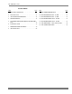
035-18496-000-C-1102 LIST OF TABLES Tbl.# Pg.# Tbl.# Pg.# 1 UNIT APPLICATION DATA . . . . . . . . . . . . . . . . . . . . . 5 9 2 PHYSICAL DATA . . . . . . . . . . . . . . . . . . . . . . . . . . . . . 6 10 FAN PEFORMANCE DATA - 25 TON . . . . . . . . . . . . 21 3 UNIT MOUNTING DIMENSIONS . . . . . . . . . . . . . . . . 12 11 FAN PEFORMANCE DATA - 30 TON . . . . . . . . . . . . 21 4 CORNER WEIGHTS . . . . . . . . . . . . . . . . . . . . . . . . . . 12 12 FAN PERFORMANCE DATA - 40 TON . . . .
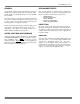
035-18496-000-C-1102 GENERAL REPLACEMENT PARTS The LA and LB evaporator units are designed for use with the HA/HB Series condensing units.Units are designed to match up with LA/LB series Evaporator Blowers to meet ASHRAE 90.1 standards. Refer to parts manual for complete listing of replacement parts on this equipment.
035-18496-000-C-1102 INDOOR PRODUCT NOMENCLATURE L A 300 C 00 A 6 A AA 1 L Model Number Description Product Category A Product Identifier 300 Nominal Cooling Capacity MBH Model # C 00 A 6 A AA 1 Options L = Air Handling Unit A = R-22 Standard Efficiency 2-Pipe B = R-22 Standard Efficiency 4-Pipe 300 = 25 Ton 360 = 30 Ton 480 = 40 Ton 600 = 50 Ton C = Cooling Only 00 = No Heat Installed Heat Type Nominal Heating Capacity Airflow Options Voltage Installation Options Additional Options Product Gener
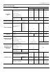
035-18496-000-C-1102 TABLE 2: PHYSICAL DATA MODEL DESCRIPTION LA300 LB360 LB480 LB600 4 x 40 4 x 40 4 x 50 4 x 62 93 93 96 96 Face Area, Feet2 25.8 25.8 33.3 41.
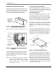
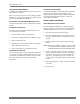
035-18496-000-C-1102 BLOWER MOTOR MOUNTING LOCATIONS Units are shipped from the factory less motor and drives. The blower motor and drive packages are ordered and shipped separately for field mounting. However, the units are shipped with the motor mounting assembly installed as shown in 1 for the LA300, LB360, LB480 and 2 for the LB600. LA300/LB360/LB480 MOTOR MOUNTING The LA300, LB360 and LB480 ship from the factory with a motor mounting adapter plate for use with the 7.5 and 10 HP motors.
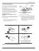
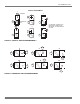
035-18496-000-C-1102 MOTOR MOUNT ARRANGEMENTS The motor mounting arrangement can be changed to allow motor access based on the airflow arrangement required. The recommended motor location for each blower arrangement is as follows. M O T O R M O T O R M O U N T IN G C H A N N E L S M O T O R M O U N T IN G P L A T E LA300/LB360/LB480 MOTOR ARRANGEMENTS The LA300, LB360 and LB480 units are shipped with the motor mount in location A as shown in 4.
035-18496-000-C-1102 LB600 MOTOR ARRANGEMENTS ALTERNATE POSITION THREE The LB600 unit is shipped with the motor mount in the standard location as shown in 2. The motor mounting plate, the pivot bolts and the adjustment screws can be moved into a position similar to the one detailed in alternate position one but behind the other blower scroll. The framework behind each blower scroll has the same bolthole arrangement.
035-18496-000-C-1102 VERTICAL ARRANGEMENTS 1 AIR BLOWER 3 2 AIR AIR AIR EVAPORATOR COIL AIR A IR * AIR 4 * IF REQUIRED, SOME AIR CAN BE BROUGHT THROUGH THE BOTTOM OF THE EVAPORATOR SECTION.
035-18496-000-C-1102 LB600 AIR DISCHARGE The LB600 blower and coil section are shipped separately and must be joined in the field. The blower section can be mounted either above the coil for a vertical positioning or beside the coil for horizontal positioning. Both vertical and horizontal positions can be arranged for upward, downward, or horizontal air discharge. NOTE: Ductwork should never be used to support the blower section.
035-18496-000-C-1102 TABLE 3: UNIT MOUNTING DIMENSIONS DIMENSIONS, INCHES LA/LB UNIT 300 AX 69-1/4 BX 49-1/16 CX 26-5/8 360 69-1/4 49-1/16 26-5/8 480 84 50-9/16 34 MOUNTING The evaporator blower may be suspended from the joists with isolation type hangers or hooks. Suspension accessory 1HH0403, which includes three suspension channels and hardware, may be ordered separately. The channels extend across the evaporator coil section, the heating coil section (if included) and the blower section.
035-18496-000-C-1102 NOTE: The following illustration shows how the channels should be secured to the unit using the hardware provided with the suspension accessory.
035-18496-000-C-1102 D = 2 9 5 L B S . E = 3 0 0 L B S . A = 2 7 5 L B S . S U S P E N S IO N C H A N N E L S 1 B = 2 8 0 L B S . 1 2 F = 3 1 0 L B S . 2 2 1 2 C = 2 8 5 L B S .
035-18496-000-C-1102 O U T S ID E C H A N N E L 9 /1 6 " H O L E F O R 1 /2 " H A N G E R (2 P E R C H A N N E L ) S U S P E N S IO N C H A N N E L 5 /1 6 -1 8 " H E X N U T 5 /1 6 -1 8 " H E X N U T L O C K W A S H E R R O D 9 /1 6 " F L A T W A S H E R S P A C E R (3 /8 " L O N G ) T O P P A N E L 9 /1 6 " F L A T W A S H E R S ID E P A N E L M A C H IN E S C R E W (5 /1 6 -1 8 X 1 -1 /2 L G ) O U T E R F R A M E O F U N IT S E C T IO N (1 -3 /4 " X 1 -3 /4 ") C E N T E R C H A N N E L ( L o c
035-18496-000-C-1102 DUCT TRANSITION NON-FLAMMABLE COLLAR DUCT 24" AIR OUTLET BLOWER GASKETS (BY INSTALLER) FLANGED DUCT CONNECTION (FIELD FABRICATED) FIGURE 13 - SUGGESTED METHOD FOR CONNECTING DUCTWORK RETURN AIR DUCT ANGLES Return air duct angles are shipped turned in. They are intended to be unscrewed and turned for connection of ductwork. The return air grille accessory attaches in the same manner as the panels.
035-18496-000-C-1102 Suitable hangers, brackets or clamps should support the refrigerant lines. Braze all copper-to-copper joints with Silfos-5 or equivalent brazing material. Do not use soft solder. Never braze or solder the liquid and suction lines together. The complete suction line should be insulated with no less than ½" Armaflex or equivalent. If it is desirable to tape or wire the liquid and suctions lines together for support purposes, they must be completely insulated from each other.
035-18496-000-C-1102 PUMP OUT The pump out function is a standard feature on the 25 to 50 ton systems. The pump out circuit is activated each time the first and third compressor stage is called for by the thermostat. As such, it’s a “Pump Out On Start Up” design. A normally closed solenoid valve (POS1, 2, 3 or 4) is placed in the liquid line, just prior to expansion valve. When cooling is not being called for by the thermostat, the pump out solenoid (POS) is not energized, so it’s in the closed position.
035-18496-000-C-1102 Check belt tension. Drive packages are supplied with fiberglass belts that must be properly tensioned at installation because they do not stretch. The belt should deflect 3/16" per foot of belt span with a 2 or 3-pound force. Alignment of the resilient motor mount can be corrected by adjustment at the slots on the end opposite the pulleys.
035-18496-000-C-1102 TABLE 8: UNIT DRIVE DATA ADJUSTABLE MOTOR PULLEY UNIT MODEL LA300 LB360 LB480 LB600 DRIVE KIT MODEL NUMBER BLOWER RPM RANGE 1LD0440 1LD0407 FIXED BLOWER PULLEY BORE (IN.) BELTS PITCH LENGTH (IN.) PITCH DIA. (IN.) BORE (IN.) PITCH DIA. (IN.) 600 - 750 4.0 - 5.0 1 1/8 12.0 1 3/16 2 63.3 A62 700 - 850 4.2 - 5.2 1 3/8 11.0 1 3/16 2 63.3 A62 1LD0442 780 - 940 5.3 - 6.3 1 3/8 12.0 1 3/16 2 63.3 A62 1LD0415 636 - 795 4.0 - 5.0 1 3/8 11.
035-18496-000-C-1102 TABLE 10: FAN PEFORMANCE DATA - 25 TON CFM RPM 8,000 9,000 10,000 11,000 12,000 SP BHP kW SP BHP kW SP BHP kW SP BHP kW SP BHP kW 600 - - - 0.30 2.5 2.3 0.20 3.1 2.9 0.02 3.6 3.4 - - - 635 0.56 2.4 2.3 0.43 2.7 2.6 0.31 3.3 3.1 0.13 3.8 3.5 - - - 700 0.80 3.0 2.8 0.68 3.3 3.1 0.54 3.7 3.5 0.38 4.2 3.9 0.20 4.8 4.5 775 1.12 3.7 3.4 1.00 4.0 3.7 0.85 4.4 4.1 0.70 4.8 4.5 0.54 5.3 5.0 800 1.23 3.9 3.
035-18496-000-C-1102 7/8 KNOCKOUTS FOR POWER AND CONTROL WIRING AIR OUT M AIR OUT K 5/8 5/8 L K F J D G KNOCKOUT FOR LIQUID PIPING H C E { LESS BOTTOM PANEL BLOWER SECTION AIR IN D KNOCKOUT FOR SUCTION PIPING AIR IN KNOCKOUT FOR DRAIN PIPING EVAPORATOR COIL SECTION A 5/8 PANEL See detailed drawings for piping and drain connections on following pages.
035-18496-000-C-1102 LIQUID SYS. #1 LIQUID SUCTION LIQUID SYS. #2 SUCTION SYS. #2 SYS.
035-18496-000-C-1102 FIGURE 23 - UNIT DIMENSIONS 4.7" 13.5" Liquid Line Sys. #1 4.0" 10.1" Liquid Line Sys. #2 3.8" 24.0" SUCTION LINE SYS. #2 3.0" 23.86" 2.1" 6.0" 13.5" Condensate Drain 3.0" 6.7" SUCTION LINE SYS.
035-18496-000-C-1102 To check the supply air CFM after the initial balancing has been completed: 1. Drill two (2) 5/16-inch holes in the side panel as shown in Figure 24. 2. Insert at least 8 inches of 1/4 inch tubing into each of these holes for sufficient penetration into the airflow on both sides of the evaporator coil. 3. 4. Using an inclined manometer, determine the pressure drop across a dry evaporator coil.
035-18496-000-C-1102 I.W.C. 25-ton Pressure Drop Across Indoor Coil 1.00 0.90 0.80 0.70 0.60 0.50 0.40 0.30 0.20 0.10 0.00 7000 8000 9000 10000 11000 12000 13000 CFM FIGURE 26 - 25-TON PRESSURE DROP VS. CFM ACROSS INDOOR COIL 30-ton Pressure Drop Across Indoor Coil 0.70 0.60 I.W.C. 0.50 0.40 0.30 0.20 0.10 0.00 9000 10000 11000 12000 13000 14000 15000 CFM FIGURE 27 - 30-TON - PRESSURE DROP VS.
035-18496-000-C-1102 40-ton Pressure Drop Across Indoor Coil 0.70 0.60 I.W.C. 0.50 0.40 0.30 0.20 0.10 0.00 12000 14000 16000 18000 20000 CFM FIGURE 28 - 40 TON - PRESSURE DROP VS. CFM ACROSS INDOOR COIL (DOMESTIC) 50-ton Pressure Drop Across Indoor Coil 0.70 0.60 I.W.C. 0.50 0.40 0.30 0.20 0.10 0.00 15000 17000 19000 21000 23000 25000 CFM FIGURE 29 - 50 TON - PRESSURE DROP VS.
035-18496-000-C-1102 FIGURE 30 - INDOOR UNIT WIRING DIAGRAM LB360, 480 & 600 28 Unitary Products Group
035-18496-000-C-1102 FIGURE 31 - INDOOR WIRING DIAGRAM LA300 Unitary Products Group 29
035-18496-000-C-1102 30 Unitary Products Group
035-18496-000-C-1102 Unitary Products Group 31
035-18496-000-C-1102 Subject to change without notice. Printed in U.S.A. Copyright © by Unitary Products Group 2002. All rights reserved.