
- ETL - Energy Technology Laboratories Air Conditioner User Manual


FORM 145.32-IOM1 (908)
13
JOHNSON CONTROLS
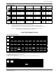
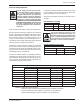
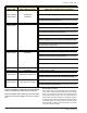
STANDARD MOTORS
MODEL
VOLTAGE COMPRESSOR EVAPORATOR FAN CONDENSER FAN MIN. CCT. "MOP"
#
QTY RLA LRA HP FLA HP FLA AMPACITY
Max Overcurrent
Prot.
AC024H12 208-230/1/60 1 @ 13.5 58.3 0.25 2.6 0.50 4.5 23.98 35
AC024H32 208-230/3/60 1 @ 8.6 55.0 0.25 1.4 0.50 2.2 14.35 20
AC036H12 208-230/1/60 1 @ 14.1 77.0 0.33 3.3 0.75 5.5 26.43 40
AC036H32 208-230/3/60 1 @ 9.0 71.0 0.33 1.6 0.75 2.6 15.45 20
AC036H34 460/3/60 1 @ 5.6 38.0 0.33 0.8 0.75 1.3 9.10 15
AC036H35 575/3/60 1 @ 3.8 36.5 0.50 0.9 0.75 1.0 6.63 15
AC048H12 208-230/1/60 1 @ 19.9 109.0 0.75 5.5 1.00 6.3 36.68 50
AC048H32 208-230/3/60 1 @ 13.1 83.1 0.75 2.6 1.00 3.3 22.28 35
AC048H34 460/3/60 1 @ 6.1 41.0 0.75 1.3 1.00 1.5 10.43 15
AC048H35 575/3/60 1 @ 5.0 34.0 0.75 1.0 1.00 1.1 8.35 15
AC060H32 208-230/3/60 1 @ 16.0 110.0 1.00 3.3 1.50 4.6 27.90 40
AC060H34 460/3/60 1 @ 7.8 52.0 1.00 1.5 1.50 2.1 13.35 20
AC060H35 575/3/60 1 @ 5.7 38.9 1.00 1.1 1.50 1.7 9.93 15
Notes:
Data shown for packaged unit installation, with single point power supply.
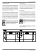
For split installation with separate evaporator motor power supply, calculate MCA and MFS as follows -
Min. Circuit Ampacity ( MCA ) = 1.25 X Largest motor amps (FLA or RLA) + sum of the remaining motor amps
Max Fuse / Cct. Bkr Size ( MFS ) = 2.25 X Largest motor amps + sum of the remaining motor amps
Select next smallest NEC listed fuse size from calculated value
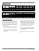
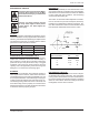
FAN PERFORMANCE DATA
SUPPLY AIR BLOWER PERFORMANCE
EXTERNAL STATIC PRESSURE - Inches W.C.
MODEL SUPPLY 0.2 0.4 0.6 0.8 1.0 1.2 1.4 1.6 1.8
CFM RPM BHP RPM BHP RPM BHP RPM BHP RPM BHP RPM BHP RPM BHP RPM BHP RPM BHP
700
593 0.06 755 0.10 915 0.13 1048 0.17 1175 0.23
- - - - - - - -
2 TON
800
629 0.08 777 0.12 914 0.16 1169 0.20 1178 0.25
- - - - - - - -
900
668 0.11 804 0.15 930 0.19 1170 0.24 - -
- - - - - - - -
1000
598 0.11 722 0.16 835 0.19 930 0.25 1141 0.32
- - - - - - - -
3 TON
1200
727 0.20 831 0.25 929 0.31 972 0.33
- - - - - - - - - -
1400
747 0.26 844 0.32
- - - - - - - - - - - - - -
1450
595 0.22 661 0.27 745 0.31 836 0.38 909 0.45 982 0.52 1046 0.61 - - - -
4 TON
1600
601 0.26 691 0.33 773 0.39 847 0.44 921 0.51 987 0.61 1056 0.67 - - - -
1800
652 0.35 735 0.42 812 0.5 883 0.57 948 0.64 1018 0.72 - - - - - -
1800
583 0.30 674 0.37 755 0.44 830 0.52 900 0.59 966 0.69 1037 0.75 - - - -
5 TON
2000
688 0.45 767 0.53 839 0.61 907 0.69 971 0.77 1029 0.85 1086 0.92 - - - -
2200
677 0.5 754 0.59 826 0.68 894 0.77 957 0.86 1018 0.95 - - - - - -
NOTE:
1. At higher evaporator airflows and wet bulb conditions, condensate carry-over may occur. Adjust airflow downward as necessary.
2. Values include pressure drop from wet coil and clean filters.
3. Shaded areas indicate oversize motors
4. Adjustment limits of standard factory-installed drives are indicated by bold borders. (See pulley data on Pg. 17)
CONDENSER AIR BLOWER PERFORMANCE
EXTERNAL STATIC PRESSURE - Inches W.C.
MODEL OUTDOOR 0.2 0.4 0.6 0.8 1.0 1.2 1.4 1.6
CFM RPM BHP RPM BHP RPM BHP RPM BHP RPM BHP RPM BHP RPM BHP RPM BHP
2 TON 1600
750 0.29 852 0.35 948 0.42 996 0.46 - - - - - - - -
3 TON 1950
864 0.47 949 0.55 1032 0.63 1112 0.72 - - - - - - - -
4 TON 2500
645 0.53 749 0.63 812 0.74 872 0.86 945 0.98 - - - - - -
5 TON 2900
723 0.79 800 0.84 871 1.07 935 1.20 996 1.55 1057 1.42 - - - -
DSH
DSH
DSH
DSH
DSH
DSH
DSH
DSH
DSH
DSH
DSH
DSH
DSH
14)