New Release Model DSH Ceiling Mounted Ducted R-410A Air Conditioning Units Form 145.
FORM 145.32-IOM1 (908) IMPORTANT! READ BEFORE PROCEEDING! GENERAL SAFETY GUIDELINES This equipment is a relatively complicated apparatus. During installation, operation, maintenance or service, individuals may be exposed to certain components or conditions including, but not limited to: refrigerants, oils, materials under pressure, rotating components, and both high and low voltage. Each of these items has the potential, if misused or handled improperly, to cause bodily injury or death.
FORM 145.32-IOM1 (908) Changeability of this document In complying with Johnson Controls policy for continuous product improvement, the information contained in this document is subject to change without notice. While Johnson Controls makes no commitment to update or provide current information automatically to the manual owner, that information, if applicable, can be obtained by contacting the nearest Johnson Controls service office.
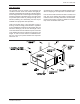
FORM 145.32-IOM1 (908) GENERAL INFORMATION Our units are designed to meet the ever-changing (unique) installation requirements of today’s market. The horizontal configuration is unitized for single package or split installation. Low profile design allows the unit to be installed on the floor or suspended from the ceiling. All unit components are securely mounted inside the heavy gauge “Galvalume” sheet metal cabinet. All units are lined with a 1/2 in.
FORM 145.
FORM 145.32-IOM1 (908) PRE-INSTALLATION INSPECTION OF EQUIPMENT All units are factory tested to ensure safe operation and quality assembly. Units are packaged and sealed on shipping skids and shipped in first class condition. Torn and broken packaging, scratched or dented panels should be reported to carrier immediately. An internal inspection of each unit should be performed prior to installation. Remove all access doors and check for visual defects that can occur during transport.
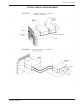
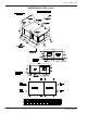
FORM 145.32-IOM1 (908) UNIT MOUNTING The 2 through 5 ton unit consist of an evaporator and condenser module. These two modules are rigidly attached by a joining strip across the top of the two cabinet, and two long side cross-member angles which bridge the mounting channels on the bottom of the unit. These units may be field split to allow for passage through doors, elevators, hallways, etc. Alternatively, the units may be installed as a split system after separation. A minimum of 4-in.
FORM 145.32-IOM1 (908) SEPARATION OF UNITS The 2 through 5 ton units are provided with refrigerant shut-off valves to allow the evaporator and condenser sections to be field split - without the necessity of reclaiming the entire unit refrigerant charge.
FORM 145.
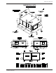
FORM 145.32-IOM1 (908) DIMENSIONAL DATA (Cont.
FORM 145.32-IOM1 (908) DUCTWORK When installing ductwork, adhere to local Codes and sensible practice. Minimize duct runs and avoid abrupt changes in direction where possible. Allow ample access space for servicing of the coils and changing of filters. Perform regular maintenance on ducts to increase unit life, maintain efficient operation, and reduce accumulation of explosive dust.
FORM 145.32-IOM1 (908) ELECTRICAL WIRING PACKAGED UNIT Follow local electrical codes when making electrical connections. Units are completely factory wired for normal supply voltages (ie.208-230, 460, 575/3phase/60Hz) Confirm unit specifications by checking unit data plate. The factory wiring terminates in two boxes, one in each section of the unit. The electrical control boxes are located behind outer access panels. Each electrical compartment has its own control cover.
FORM 145.32-IOM1 (908) STANDARD MOTORS VOLTAGE MODEL COMPRESSOR 1 1 @ @ 13.5 8.6 58.3 55.0 HP 0.25 0.25 FLA 2.6 1.4 HP 0.50 0.50 FLA AMPACITY "MOP" Max Overcurrent Prot. 23.98 14.35 35 20 208-230/1/60 208-230/3/60 460/3/60 575/3/60 1 1 1 1 @ @ @ @ 14.1 9.0 5.6 3.8 77.0 71.0 38.0 36.5 0.33 0.33 0.33 0.50 3.3 1.6 0.8 0.9 0.75 0.75 0.75 0.75 5.5 2.6 1.3 1.0 26.43 15.45 9.10 6.
FORM 145.32-IOM1 (908) MOTOR AND PULLEY DATA EVAPORATOR - STANDARD BLOWER MOTOR AND DRIVE DATA Adjustable Motor Drive Range Motor Pulley Model (RPM) Browning # Frame Eff.(%) Pitch Dia.(in) HP 2 TON 3 TON 4 TON 5 TON 845-1170 675-1010 675-1010 745-1120 1/4 1/3 3/4 1 56 56 56 143 66.0 75.0 75.0 75.0 2.6-3.6 2.0-3.0 2.0-3.0 2.0-3.0 1VP40 X 5/8 1VP34 X 5/8 1VP34 X 5/8 1VP34 X 7/8 CONDENSER - STANDARD BLOWER MOTOR AND DRIVE DATA Adjustable Motor Drive Range Motor Pulley Model (RPM) Browning # Frame Eff.
FORM 145.32-IOM1 (908) START-UP AND OPERATION Prior to starting unit for the first time, turn the thermostat system switch to OFF - or raise the cooling setpoint to the highest temperature, to prevent the unit from starting. Close the electrical disconnect switch. This will energize the compressor crankcase heater(s). WAIT A MINIMUM OF FOUR HOURS BEFORE STARTING THE SYSTEM. This period will allow the crankcase heater to vaporize any liquid refrigerant in the compressor crankcase.
FORM 145.
FORM 145.32-IOM1 (908) MAINTENANCE / SERVICE Disconnect And Lock Out Power When Servicing Unit. Failure To Do So May Result In Personal Injury Or Death Due To Electrical Shock. DRIVE BELTS Examine belts periodically for wear. Glazed areas on the drive surfaces indicate overheating due to belt slippage. Ideal tension is the lowest tension at which the belt will not slip under peak load conditions. Over-tensioning shortens belt and bearing life.
FORM 145.32-IOM1 (908) COMFORT ALERT™ DIAGNOSTICS The Comfort Alert diagnostics module is a breakthrough innovation for troubleshooting and protecting three phase Copeland Scroll® compressors. The module installs easily in the electrical box of the condensing unit near the compressor contactor. By monitoring and analyzing data from the Copeland Scroll compressor and the thermostat demand, the module can accurately detect the cause of electrical and system related failures and protect the compressor.
FORM 145.32-IOM1 (908) Status LED Green “POWER” Status LED Description Module has power Status LED Troubleshooting Information Supply voltage is present at module terminals Red “TRIP” LED Thermostat demand signal Y 1. Compressor protector is open On Solid is present, but the compressor is not running 2. Condensing unit power disconnect is open 3. Compressor circuit breaker or fuse(s) is open 4. Broken supply wires or connector is not making contact 5.
FORM 145.32-IOM1 (908) Status LED Status LED Description Yellow “ALERT” Flash Code 4 Locked Rotor LOCKOUT Status LED Troubleshooting Information 1. Low line voltage to compressor 2. Excessive liquid refrigerant in compressor 3. Compressor bearings are seized Yellow “ALERT” Flash Code 5 Open Circuit 1. Condensing unit power disconnect is open 2. Compressor circuit breaker or fuses are open 3. Compressor contactor has failed open 4. High pressure switch is open and requires manual reset 5.
FORM 145.32-IOM1 (908) Miswiring the Comfort Alert module will cause false LED codes. Table 1 describes LED operation when the module is miswired and what troubleshooting action is required to correct the problem. table 1 - comfort alert module troubleshooting Installation Verification To verify the installation of Comfort Alert is correct, a functional test can be performed. Force a call for cooling and when the compressor starts to run, monitor the yellow ALERT LED.
FORM 145.32-IOM1 (908) LIMITED WARRANTY ONE YEAR LIMITED WARRANTY Johnson Controls warrants this product to be free from defects in workmanship or material for a period of one year from date of original installation or 18 months from date of shipment, whichever comes first.
FORM 145.32-IOM1 (908) R-410A QUICK REFERENCE GUIDE Refer to Installation Instructions for specific installation requirements. • R-410A Refrigerant operates at 50 - 70 percent higher pressures than R-22. Be sure that servicing equipment and replacement components are designed to operate with R-410A. • R-410A Refrigerant cylinders are rose colored. • Recovery cylinder service pressure rating must be 400 psig. DOT 4BA400 or DOT BW400. • Recovery equipment must be rated for R-410A.
Subject to change without notice. Printed in U.S.A. Copyright© 2008 by Unitary Products Group. All rights reserved. Engineered Systems Products Group Form 145.32-IOM1 (908) New Release P.O.