INSTALLATION INSTRUCTION SUNLINE GAS/ELECTRIC SINGLE PACKAGE AIR CONDITIONERS CONTENTS GENERAL . . . . . . . . . . . . . . . . . . . . . . . . . . . . . . . . . 3 SAFETY CONSIDERATIONS . . . . . . . . . . . . . . . . . . 3 AGENCY APPROVALS . . . . . . . . . . . . . . . . . . . . . . 4 INSPECTION . . . . . . . . . . . . . . . . . . . . . . . . . . . . . . . 4 INSTALLATION . . . . . . . . . . . . . . . . . . . . . . . . . . . . 4 OPERATION . . . . . . . . . . . . . . . . . . . . . . . . . . . . . .
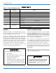
035-17233-000-C-0702 TABLE OF CONTENTS GENERAL . . . . . . . . . . . . . . . . . . . . . . . . . . . . . . . . . . . . . . 3 SAFETY CONSIDERATIONS . . . . . . . . . . . . . . . . . . . . . . . 3 FILTERS . . . . . . . . . . . . . . . . . . . . . . . . . . . . . . . . . . . . . . . . . . . . . . . . MOTORS . . . . . . . . . . . . . . . . . . . . . . . . . . . . . . . . . . . . . . . . . . . . . . . . OUTDOOR COIL . . . . . . . . . . . . . . . . . . . . . . . . . . . . . . . . . . . . . . . . . .
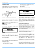
035-17233-000-C-0702 D 1 HG 180 E 180 25 EC TABLE 1: PRODUCT NOMENCLATURE Model # Model Number Description D Product Category 1 Product Generation 1 = 1st Generation HG Product Identifier HG = Gas/Electric 180 Nominal Cooling Capacity E Factory Installed Heat 018 Nominal Heating Capacity 25 Voltage Code EC Factory Installed Option Code Options D = Air Cond.
035-17233-000-C-0702 INSTALLATION LIMITATIONS Improper installation may create a condition where the operation of the product could cause personal injury or property damage. These units must be installed in accordance with the following national and local safety codes: 1. National Electrical Code ANSI/NFPA No. 70. REFERENCE 2. National Fuel Gas Code Z223.1. Additional information on the design, installation, operation and service of this equipment is available in the following reference forms: 3.
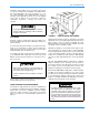
035-17233-000-C-0702 LOCATION Use the following guidelines to select a suitable location for these units. 1. Unit is designed for outdoor installation only. 2. Condenser coils must have an unlimited supply of air. Where a choice of location is possible, position the unit on either north or east side of building. Excessive exposure of this furnace to contaminated combustion air may result equipment damage or personal injury.
035-17233-000-C-0702 combustion and ventilation air in accordance with Section 5.3, Air for Combustion and Ventilation of the National Fuel Gas Code, ANSI Z223.1 (in U.S.A.) or Sections 7.2, 7.3 or 7.4 of Gas Installation Codes CAN/CGA-B149.1 and .2 (in Canada) and/or applicable provisions of the local building codes. Refer to Table 8 for the clearances required for combustible construction, servicing, and proper unit operation.
035-17233-000-C-0702 CONDENSATE DRAIN Plumbing must conform to local codes. Use a sealing compound on male pipe threads. Install a condensate drain line from the 1" NPT female connection on the unit to an open drain. • • • • • Side Supply & Return Air compartments (Two panels) Blower compartment (Three panels) Main control box Filter compartment Outdoor Air compartment (Two panels) Refer to Figure 10 for location of these access panels.
035-17233-000-C-0702 Typical supply piping arrangements are shown in Figures 6 and 7. All shaded items are field-supplied. When connecting electrical power and control wiring to the unit, waterproof type connectors MUST BE USED so that water or moisture cannot be drawn into the unit during normal operation. The above waterproofing conditions will also apply when installing a field-supplied disconnect switch.
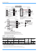
035-17233-000-C-0702 C O N T R O L W IR IN G C O O L IN G O N L Y (2 4 V O L T T H E R M O S U N IT T E R M B L O C K 1 T H E R M O S T A T 1 R T E R M IN A L S Y Y W R W G Y 1 2 4 V o lt ( w ith S T e r m in a o f th e 2 1 o s ta t 2 T e 2 T B 0 4 1 T B - lo n tro l b o x Y 2 W 1 2 4 V O L T T R A N S F O R M E R W 2 Y 2 W 2 G B X 3 G 4 N O T U S E D A 1 4 C O M A 1 A 2 T A D D J U M P E R 2 3 U N IT T E R M IN A L B L O C K 1 T B 2 R Y 1 Y 2 W 1 W 1 W 2 B L E D 1 L E D 2 1 O N L Y (2
035-17233-000-C-0702 TABLE 5: PIPE SIZING1 Nominal Iron Pipe Size Length in Feet 1 1 in. 1-1/4 in. 10 520 1,050 20 350 730 30 285 590 40 245 500 50 215 440 60 195 400 70 180 370 80 170 350 90 160 320 100 150 305 Maximum capacity of pipe in cubic feet of gas per hour. (Based upon a pressure drop of 0.3 inch water column and 0.6 specific gravity gas.) FIGURE 7 : BOTTOM SUPPLY CONNECTION EXTERNAL SHUT-OFF L.P.
035-17233-000-C-0702 Check all connections for leaks when piping is completed, using a soap solution. NEVER USE A FLAME. VENT AND COMBUSTION AIR HOODS Two vent hoods and a combustion air hood (with screens) are shipped attached to the blower housing in the blower compartment. These hoods must be installed to assure proper unit function. All hoods must be fastened to the outside of the gas heat access panel with the screws provided in the bag also attached to the blower housing.
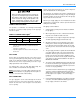
035-17233-000-C-0702 FIGURE 9 : ENTHALPY SETPOINT ADJUSTMENT 12 Unitary Products
035-17233-000-C-0702 TABLE 6: PHYSICAL DATA TABLE 7: DHG VOLTAGE LIMITATIONS1 DHG MODELS 180 240 POWER SUPPLY Centrifugal Blower (Dia. x Wd. in.) 15 x 15 18 x 15 Fan Motor HP 5 Rows Deep VOLTAGE MIN. MAX. 208/230-3-60 187 253 7.5 460-3-60 414 506 4 4 575-3-60 518 506 Fins Per Inch 13.5 13.5 Face Area (Sq. Ft. 15.5 20.0 CONDENSER FANS (Two Per Unit) Propeller Dia. (in.) (Each) 30 30 Fan Motor Hp (Each) 1 1 Nom.
035-17233-000-C-0702 BLOWER ACCESS BLOWER MOTOR ACCESS ECONOMIZER / MOTORIZED DAMPER, FIXED OUTDOOR INTAKE AIR AND POWER EXHAUST RAIN HOODS (See detail "Y") COMPRESSOR ACCESS FIELD-SUPPLIED DISCONNECT SWITCH LOCATION BLOWER COMPARTMENT ACCESS (Auxiliary) OPTIONAL COIL GUARD KIT DOT PLUG (For pressure Drop Reading) 48-5/8" (15 Ton) 52-5/8" (20 Ton) GAS HEAT ACCESS CONDENSER COILS VENT AIR OUTLET HOODS 21" 5" COMBUSTION AIR INLET HOOD 7-1/8" 125-1/4" (15 Ton) 136-1/4" (20 Ton) 6-3/8" 9-3/4" (C)
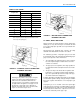
035-17233-000-C-0702 C O N D E N S E R S E C T IO N G A U G E L IN E A C C E S S E V A P O R A T O R S E C T IO N D O T P L U G (F o r p re s s u re d r o p r e a d in g ) 4 0 -3 /8 " F IL T E R A C C E S S S U P P L Y A IR R E T U R N A IR 5 -1 /2 " C O M P R E S S O R A C C E S S 1 " N P T F E M A L E C O N D .
035-17233-000-C-0702 TABLE 11: DHG 15 TON SUPPLY AIR BLOWER PERFORMANCE DHG180 - BOTTOM DUCT CONNECTIONS1, 2 BLOWER SPEED, (RPM) MOTOR PULLEY (TURNS OPEN)3 CFM 4500 4 ESP BHP 5250 3 6000 KW ESP BHP KW ESP 3 6750 BHP KW ESP 3 7200 BHP KW ESP 3 BHP KW - 208 VOLT AND STANDARD DRIVE 850 6.05 0.9 2.4 2.1 0.6 2.9 2.6 0.3 3.4 3.0 - - - - - 870 5.5 1.0 2.5 2.2 0.7 3.0 2.7 0.4 3.5 3.1 - - - - - - 915 4.5 1.1 2.6 2.4 0.8 3.1 2.8 0.5 3.6 3.2 0.
035-17233-000-C-0702 TABLE 12: DHG 20 TON SUPPLY AIR BLOWER PERFORMANCE DHG240 - BOTTOM DUCT CONNECTIONS1, 2 BLOWER SPEED, (RPM) MOTOR PULLEY (TURNS OPEN)3 CFM 6000 ESP 4 BHP 7000 KW ESP 4 8000 4 9000 BHP KW ESP BHP KW ESP 4 9400 BHP KW ESP 4 BHP KW 208 VOLT AND STANDARD DRIVE 870 6.05 1.3 3.6 3.0 0.7 4.3 3.7 0.2 5.1 4.3 - - - - - - 900 5.0 1.4 3.8 3.2 0.9 4.7 4.0 0.4 5.6 4.7 - - - - - - 930 4.0 1.6 4.1 3.4 1.1 5.0 4.2 0.6 5.9 5.0 0.1 6.
035-17233-000-C-0702 TABLE 13: STATIC RESISTANCES1 RESISTANCE, IWG CFM DESCRIPTION 15 TON 20 TON 4500 5765 7200 6000 7000 9400 WET COIL 0.1 0.1 0.1 0.1 0.1 0.1 ECONOMIZER OPTION 0.1 0.1 0.1 0.1 0.1 0.1 HORIZONTAL DUCT CONN.2 0.2 0.3 0.5 0.2 0.3 0.5 1 Deduct these resistance values from the available unit ESP values listed in the respective blower performance table except for Horizontal Duct Connections. 2 Add these values due to less airflow resistance.
035-17233-000-C-0702 OPERATION COOLING SYSTEM The cooling section is a complete factory package utilizing an air-cooled condenser. The system is factory-charged with Refrigerant-22. The compressors are hermetically sealed, internally sprung and base-mounted with rubber-insulated hold-down bolts. Compressors have inherent (internal) protection. If there is an abnormal temperature rise in a compressor, the protector will open to shut down the compressor.
035-17233-000-C-0702 3. A Low Pressure Switch/Loss Of Charge to protect against loss of refrigerant charge. (Opens at 7 psig + 3 and resets at 22 psig + 5) If either one of the above safety controls opens, that individual refrigerant system will be locked out. The other refrigerant system will continue in operation unless it too is effected by the same fault. The lock out of either system can be reset by opening the 24V circuit either at the room thermostat or at the unit disconnect.
035-17233-000-C-0702 TABLE 16: LIMIT CONTROL SETTING IG N . C O N T R O L # 2 Input Output 15 & 20 300 240 195 15 & 20 400 320 195 IG N . C O N T R O L # 1 R O L L O U T S W . G V 1 G A S V A L V E S E N S O R # 1 G V 2 G A S V A L V E IG N IT O R # 2 IG N IT O R # 1 S E N S O R # 2 Capacity, MBH Limit Control Opens, °F Units (Tons) HEAT ANTICIPATOR SETPOINTS It is important that the anticipator setpoint be correct.
035-17233-000-C-0702 5. Set room thermostat to desired temperature.(If thermostat set temperature is above room temperature, pilot burner ignition will occur and, after an interval to prove pilot flame, main burners will ignite). TO SHUT DOWN: 1. Turn off electric power to unit. 2. Depress knob of gas valve while turning to off position. Adjust as follows: 1. Remove the cap on the regulator. It's located next to the push-on electrical terminals. 2.
035-17233-000-C-0702 Reverse the above procedure to replace the assemblies. Make sure that burners are level and seat at the rear of the heat exchanger. Procedure for adjusting belt tension: 1. Loosen nuts (A) (top and bottom). 2. Adjust the tension by turning bolt (B). 3. Never loosen nuts (C) from each other. 4. Use a belt tension checker to apply a perpendicular force to one belt at the midpoint of the span as shown.
035-17233-000-C-0702 2. With the furnace turned on, measure the time needed for one revolution of the hand on the smallest dial on the meter. A typical gas meter usually has a 1/2 or a 1 cubic foot test dial. 3. Using the number of seconds for each revolution and the size of the test dial increment, find the cubic feet of gas consumed per hour from Table 18.
035-17233-000-C-0702 MAINTENANCE NORMAL MAINTENANCE Prior to any of the following maintenance procedures, shut off all electric power to the unit to prevent personal injury. Periodic maintenance normally consists of changing or cleaning filters and (under some conditions) cleaning the main burners FILTERS Inspect once a month. Replace disposable or clean permanent type as necessary. DO NOT replace permanent type with disposable.
035-17233-000-C-0702 1. Remove the burner assembly as outlined in BURNER INSTRUCTIONS. 2. Remove the roof over the gas heat section. 3. At the top plate from the top draft blower housing and the top draft blower wheel. 4. Remove the screws holding the top of the flue collector box. Carefully remove the top of the flue collector box without ripping the adjacent insulation. Then remove the center divider plate separating the upper and lower flue boxes. 5.
035-17233-000-C-0702 1. The indoor blower motor is a non-inherently protected three-phase motor. Protection is provided by an overload relay for overcurrent and fuses for short circuit. If the motor fails to run, check the line voltage circuit and control voltage circuit per the following procedure: a. b. 2. If the Indoor Blower Motor does not operate, check visually that contactor M3 is pulled in.
d. If the furnace is cold, check for 24 volts at wire 241 attached to the time delay relay (ETD) located in the main control box. If 24 volts is not found, replace the ETD relay. e. If 24 volts is found at wire 241, remove the wires attached to the (ETD) and with a VOM, check for continuity across contacts 1 and 2. If none is found, the (ETD) is open and must be replaced. If there is continuity, re-attach the wires.With the draft motor running, check for 24 volts at terminal 4 of (RW1-2) and (RW2-1).