2103/2103C/2103G Modem Module Installation and Operation Guide Part #69-2003-180 Copyright © 2002. All rights reserved, Teledyne Isco, Inc.
Foreword This instruction manual is designed to help you gain a thorough understanding of the operation of the equipment. Teledyne Isco recommends that you read this manual completely before placing the equipment in service. Although Teledyne Isco designs reliability into all equipment, there is always the possibility of a malfunction. This manual may help in diagnosing and repairing the malfunction. If the problem persists, call or e-mail the Teledyne Isco Technical Service Department for assistance.
2103 Modem Module Table of Contents Section 1 Introduction 1.1 1.2 1.3 1.4 1.5 Introduction . . . . . . . . . . . . . . . . . . . . . . . . . . . . . . . . . . . . . . . . . . . . . . . . . . . . . . . . Product Description. . . . . . . . . . . . . . . . . . . . . . . . . . . . . . . . . . . . . . . . . . . . . . . . . . Identifying Module Components . . . . . . . . . . . . . . . . . . . . . . . . . . . . . . . . . . . . . . . Safety Symbols and Hazard Alerts . . . . . . . . . . . . . . . . . . . . . . .
2103 Modem Module Table of Contents Section 5 Modbus Protocol 5.1 Introduction . . . . . . . . . . . . . . . . . . . . . . . . . . . . . . . . . . . . . . . . . . . . . . . . . . . . . . . . 5.2 Operation . . . . . . . . . . . . . . . . . . . . . . . . . . . . . . . . . . . . . . . . . . . . . . . . . . . . . . . . . . 5.2.1 Establishing Communication . . . . . . . . . . . . . . . . . . . . . . . . . . . . . . . . . . . . 5.2.2 Module Addressing . . . . . . . . . . . . . . . . . . . . . . . . . . . . . . .
2103 Modem Module Table of Contents 3-5 3-6 3-7 4-1 4-2 4-3 4-4 4-5 4-6 4-7 4-8 4-9 5-1 Antenna connected to the 2103C modem. . . . . . . . . . . . . . . . . . . . . . . . . . . . . . . . . Wireless Power Control screen . . . . . . . . . . . . . . . . . . . . . . . . . . . . . . . . . . . . . . . . Wireless Power Schedule screen . . . . . . . . . . . . . . . . . . . . . . . . . . . . . . . . . . . . . . . Accessing the SIM card on the bottom of the module . . . . . . . . . . . . . . . . . . . . . .
2103 Modem Module Table of Contents vi
2103 Modem Module Section 1 Introduction 1.1 Introduction This instruction manual is designed to help you gain a thorough understanding of the operation of the 2103, 2103C, and 2103G Modem Modules. Teledyne Isco recommends that you read this manual completely before placing the equipment into service. Information in this manual pertains to the 2103 phone line modem and the 2103C and 2103G cellular modems, except for the sections specific to one method of communication or the other.
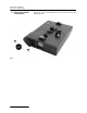
2103 Modem Module Section 1 Introduction 1.3 Identifying Module Components Figures 1-1 and 1-2 identify the key components of the 2103 Modem Module.
2103 Modem Module Section 1 Introduction 1 2 3 4 Figure 1-2 2103 Modem Components - Bottom View 1-3
2103 Modem Module Section 1 Introduction Table 1-3 2103 Modem Module Technical Specifications Dimensions Length = 10.5 inches (26.7 cm) Width = 7.5 inches (19 cm) Height = 2.9 inches (7.4 cm) Weight 2 lbs. (.9 Kg) Material High-impact molded polystyrene Enclosure NEMA 4X, 6P, IP68 (2103), IP67 (2103c) Power 6.6 to 16.6 VDC, 141 mA typical at 12 VDC, 0.
2103 Modem Module Section 1 Introduction G A F E B D C Table 1-5 2103 Communication Connector Pins (2103 only) Pin Name Description A LONA Neuron differential transceiver Data A B LONB Neuron differential transceiver Data B C VIN+ Positive power supply voltage input (+12 VDC nominal) D VIN– Negative power supply voltage input (0 VDC nominal) E RCVUP PC data receiver inverted input F XMTUP PC data transmit inverted output G Key Aligns connector pins Figure 1-3 2103 Communication Co
2103 Modem Module Section 1 Introduction Figure 1-4 2103 Modem Cable Connector 1.4 Safety Symbols and Hazard Alerts This icon identifies a general hazard and is accompanied with details about the hazard. The instruction manual identifies the hazardous condition and any steps necessary to correct the condition. The manual presents this information in one of two ways: CAUTION Cautions identify a potential hazard, which if not avoided, may result in minor or moderate injury.
2103 Modem Module Section 1 Introduction 1.5 Technical Service Although Teledyne Isco designs reliability into all of its equipment, there is always the possibility of a malfunction occurring. You can use this manual to help in diagnosing and repairing any malfunctions. If the malfunction persists, call or write the Teledyne Isco Technical Service Department for assistance: Teledyne Isco Inc. Technical Service Department P.O.
2103 Modem Module Section 1 Introduction 1-8
2103 Modem Module Section 2 Installation and Operation 2.1 Unpacking Instructions When the system arrives, inspect the contents for any damage. If there is damage, contact the delivery company and Teledyne Isco (or its agent) immediately. WARNING If there is any evidence that any items may have been damaged in shipping, do not attempt to install the unit. Please contact Teledyne Isco (or its agent) for advice. Teledyne Isco, Inc. Customer Service Dept. P.O.
2103 Modem Module Section 2 Installation and Operation hazardous environments that can prove fatal for those unprepared. These spaces are governed by OSHA 1910.146 and require a permit before entering. 2.3 Installation 2.3.1 Latches - Locking and Unlocking Follow the instructions below to install your 2103 Modem. Most of these instructions are similar for the 2103C and 2103G, but if you have one of those modules, read Section 3 or 4 for additional installation information.
2103 Modem Module Section 2 Installation and Operation 2.3.3 Stacking Modules The 2103 Modem Module can be located anywhere within a stack of up to three 2100 Series networked modules. It will draw its power from the battery module located in the stack. To connect the 2103 with a 2100 Series module, refer to the following instructions. 1. On the top of the 2100 Series module, remove the cap and stow it on the holder. This exposes the communication connector on the module. 2.
2103 Modem Module Section 2 Installation and Operation service is subject to state tariffs. Changes in Attestation Procedure for Plugs and Jacks Isco Inc. attests that the network interface plugs or jacks used on this equipment comply with and will continue to comply with the mechanical requirements specified in Part 58, sub-part F, specifically the dimensions, tolerances and metallic plating requirements. The compliance of these connectors will be assured by purchase specifications and incoming inspection.
03 Modem Module Section 2 Installation and Operation 2.4.1 Modem Cable Connection After you have installed the 2103 on the stack, you need to attach the modem cable so the module can be connected to a phone line. Remove the connector cap from the 5-pin circular modem cable connector on the right hand side of the 2103. Attach the modem cable to the connector (Figure 2-1), and then connect the other end of the modem cable to a standard telephone jack (USOC RJ-11C). Figure 2-1 Connecting the Modem Cable 2.
2103 Modem Module Section 2 Installation and Operation 2.5 Connecting to Flowlink After the 2103 is installed and the modem cable connected, you need to establish that there is a modem at the site, by configuring the module in Isco’s Flowlink software. Note The 2103 Modem requires Flowlink 4.13 or later. Earlier versions do not support the modem. Open Flowlink and go to the connect screen (Figure 2-3) by either selecting it from the pull down menu or clicking on the Quick Connect icon.
2103 Modem Module Section 2 Installation and Operation Figure 2-4 Resolution Screen Select the appropriate action on the screen to add the new modem module and then click OK. When the module has been added to the system, you will see the Measurements Screen (Figure 2-5). Figure 2-5 Measurements Screen Note If you are using a 2103C or 2103G, you need to set up a Wireless Power Control schedule at this point. For those instructions, refer to Sections 3-3 or 4-5.
2103 Modem Module Section 2 Installation and Operation Click on the Site Info tab to display that screen (Figure 2-6). Figure 2-6 Site Info Screen Select Modem under the Connection Information section. Enter the phone number to be used by the modem to connect to the site. Click Apply (F9) to apply the changes. 2.5.
2103 Modem Module Section 2 Installation and Operation 2. In the Phone Number list box, type the contact telephone numbers. These must be valid TAP access numbers. You must enter at least one number; you can enter as many as five. When an alarm condition is triggered, the system will try dialing each phone number in the list. a. To find this number, and the communications parameter settings, consult with your pager service, or go to http://www.avtech.com/Support/TAP/index.htm or to http://www.notepage.
2103 Modem Module Section 2 Installation and Operation 2.6 Pushed Data Capability The module can automatically send data to a designated server running Isco Flowlink Pro software, using 1xRTT packet-switched data transmission (2103C), GPRS packet-switched data transmission (2103G), or a land line modem (2103). The user-specified primary data transmission interval (5 minutes to 24 hours) can automatically change to a secondary interval when specific site conditions occur at the monitoring site.
2103 Modem Module Section 3 2103C Cellular Modem Module 3.1 Overview 3.1.1 Data Retrieval The 2103C Modem (part #68-2000-033 with a magnetic mount antenna; part #68-2000-030 with an in-street antenna) is a portable data retrieval unit designed to transmit data from Isco’s 2100 Series open channel flow modules. Using a computer running Isco’s Flowlink® software, you can call up your monitoring site to configure the flow module settings and retrieve flow data.
2103 Modem Module Section 3 2103C Cellular Modem Module 3.2 Antenna Options One of 2 antenna types is included with your system, also specified when ordering: • The external, magnetic mount antenna (part #68-2000-032) is 3 inches tall and has a 6 foot cable. This antenna is for general use, and is especially desirable when the system is stored within an enclosure. Figure 3-1 2103C magnetic mount antenna • The external, in-street antenna (part #68-2000-031) is 4” in diameter and 1.
2103 Modem Module Section 3 2103C Cellular Modem Module When you are ready to connect the in-street antenna to the 2103C modem, you will need to assemble the connector shell onto the end of the cable. The pieces of the connector shell are shown in Figure 3-3. An instruction sheet (P/N 60-2003506) is shipped with the antenna, and shows you the assembly steps.
2103 Modem Module Section 3 2103C Cellular Modem Module When the gold SMA connector is tightly attached to the modem, slide the connector shell forward. Press down on the metal latch on the side of the modem and push the connector shell onto the modem, as shown in Figure 3-5. Figure 3-5 Antenna connected to the 2103C modem. Note When any communication connector is not in use, it should always be capped.
2103 Modem Module Section 3 2103C Cellular Modem Module 3.3 Connecting to Flowlink The instructions for connecting to Flowlink that are in Section 2-5 apply to the 2103C. However, for the 2103C, you will also need to set up a Wireless Power Control schedule. Select the Wireless Power Control tab (Figure 3-4) and click on the Set Wireless Schedule button to set up a schedule.
2103 Modem Module Section 3 2103C Cellular Modem Module 3-6
2103 Modem Module Section 4 2103G Cellular Modem Module 4.1 Overview 4.1.1 Data Retrieval The 2103G Modem (part #68-2000-042 with a magnetic mount antenna; part #68-2000-041 with an in-street antenna) is a portable data retrieval unit designed to transmit data from Isco’s 2100 Series open channel flow modules. Using a computer running Isco’s Flowlink® software, and the appropriate cellular service, you can call up your monitoring site to configure the flow module settings and retrieve flow data.
2103 Modem Module Section 4 2103G Cellular Modem Module Figure 4-1 Accessing the SIM card on the bottom of the module It’s easiest to insert the SIM card if you set the module on its side (Figure 4-2) and push the card into its slot as shown. To remove the card from its slot, push on it and it will pop out enough that you can grasp the end and pull it out.
2103 Modem Module Section 4 2103G Cellular Modem Module 4.3 Antenna Options One of 2 antenna types is included with your system, also specified when ordering: • The external, magnetic mount antenna (part #68-2000-047) is 6 feet long and 5 inches tall. This external antenna is for general use, and is especially desirable when the system is stored within an enclosure.
2103 Modem Module Section 4 2103G Cellular Modem Module When you are ready to connect the in-street antenna to the 2103G modem, you will need to assemble the connector shell onto the end of the cable. The pieces of the connector shell are shown in Figure 4-5. An instruction sheet (P/N 60-2003506) is shipped with the antenna, and shows you the assembly steps.
2103 Modem Module Section 4 2103G Cellular Modem Module Figure 4-7 Antenna connected to the 2103G modem. Note When any communication connector is not in use, it should be capped. The cap will seal the connector to prevent corrosion, prevent moisture from entering the unit, and improve communications. Note For the transmitter to comply with FCC Maximum Permissible Exposure (MPE) regulations, the antenna needs to be located a minimum of 30 centimeters (12 inches) from the human body.
2103 Modem Module Section 4 2103G Cellular Modem Module 4.4 Connecting to Flowlink The instructions for connecting to Flowlink that are in Section 2-5 apply to the 2103G. However, for the 2103G, you may also need to set up a Wireless Power Control schedule. Note This section only applies to CSD operation, and requires the appropriate cellular service and SIM card. Select the Wireless Power Control tab (Figure 4-6) and click on the Set Wireless Schedule button to set up a schedule.
2103 Modem Module Section 4 2103G Cellular Modem Module 4.5 Setting Up The Access Point Name You may need to set up the access point that your cellular service uses. Note This section only applies to GPRS operation, and requires the appropriate cellular service and SIM card. The access point information is available from your service provider. 1. From your Windows desktop, start the HyperTerminal program (located under Accessories, Communication). 2.
2103 Modem Module Section 4 2103G Cellular Modem Module 4-8
2103 Modem Module Section 5 Modbus Protocol Sections 5.1 through 5.5 give an overview of the basic capabilities and operation of Modbus protocol as it applies to Isco 2100 Series flow modules. For a Glossary of Terms and Common Acronyms, see sections 5.4 and 5.5. For Modbus technical specifications, turn to section 5.6. 5.1 Introduction Modbus is a simple command/response mechanism to read from and write to specific memory locations called registers.
2103 Modem Module Section 5 Modbus Protocol By accessing these registers you can obtain the current value of whatever parameter you desire. The reading(s) can then be displayed or stored wherever you designate as a destination; for example, a process control computer. Note Level, flow, velocity, and temperature data is stored in metric units only. Not all registers are limited to read-only data storage. You can also use some registers for control purposes.
2103 Modem Module Section 5 Modbus Protocol 5.3 Configurations A variety of configurations can be made with Modbus, either through direct connection or through a modem. In the example shown in Figure 5-1, you are direct-connecting a server PC to two individual 2150s through Modbus, using the COM ports on the OPC Server, which are directly connected to the remote 2150s. Connection to the module is made through the RS-232 communication port on the top of the module.
2103 Modem Module Section 5 Modbus Protocol 5. OPC connects to the 2150 stack through the cable (direct connection), takes register data from the specified 2150, and populates the OPC server's holding index. 6. Process Control takes data from the OPC server's holding index and gives data to the user. Note that Process Control can be either manual or automated in this example, and that the OPC server and Process Control may be located physically on the same computer. 5.
2103 Modem Module Section 5 Modbus Protocol SCADA systems can be relatively simple, such as one that monitors the environmental conditions of a small office building, or very complex, such as a system that monitors all the activity in a nuclear power plant or a municipal water system. 5.
2103 Modem Module Section 5 Modbus Protocol 5.6 Register Specifications All numbers in the Modbus registers are stored most significant byte first. If the polling device has a byte ordering of least significant byte first (an Intel-based PC, for example), the bytes will need to be reversed after they are received. The Modbus ASCII address is used to index the data by modules. Modbus ASCII address 1 contains information related to the site.
2103 Modem Module Section 5 Modbus Protocol The register definitions for the individual modules (Modbus ASCII addresses 2-(N+1)) are in Table 5-1 below: Table 5-2 Modbus ASCII Address 2-(N+1) Register Definitions Register Number(s) Name Data Type Units Read/Write 1-4 Model number 8-byte string None Read 5-23 Module name 38-byte string None Read 241 Identify module 16 bit integer None Read/Write 2 Take reading flag 16 bit integer None Read/Write 3 26 Update interval 16 bit intege
2103 Modem Module Section 5 Modbus Protocol Table 5-2 Modbus ASCII Address 2-(N+1) Register Definitions (Continued) Register Number(s) Name Data Type Units Read/Write (1) A write to the Identify module register will cause the module to perform the identify operation which may be a steady LED for a few seconds or a beep in the Field Wizard. (2) Setting the Take Reading flag to 1 will cause the module to update the registers with current data readings.
2103 Modem Module Section 5 Modbus Protocol Table 5-2 Modbus ASCII Address 2-(N+1) Register Definitions (Continued) Register Number(s) Name Data Type Units Read/Write 238-243 Analog channel 5 time record Time 250,251 Analog channel 6 4-byte float 252 Analog channel 6 status code 16-bit integer Read 253-258 Analog channel 6 time record Time Read 265,266 Analog channel 7 4-byte float 267 Analog channel 7 status code 16-bit integer Read 268-273 Analog channel 7 time record Time Re
2103 Modem Module Section 5 Modbus Protocol 5-10
2103 Modem Module Section 6 Maintenance 6.1 Maintenance Overview This section explains the maintenance requirements of the 2103 Modem.
2103 Modem Module Section 6 Maintenance 6.3 Desiccant The 2103 Modem uses desiccant to protect the internal components from moisture damage. The cartridge is filled with indicating silica gel, which is blue or yellow when dry. As the desiccant becomes saturated, the color changes from blue to pink, or from yellow to green. Replace the desiccant before the entire length of the cartridge turns pink or green. 6.3.
2103 Modem Module Section 6 Maintenance Silica gel 6.4 Hydrophobic Filter To reactivate the silica gel desiccant, pour the spent desiccant into a heat resistant container. Never heat the cartridge assembly; it will melt. Heat the silica gel in a vented convection oven at 212° to 350°F (100° to 175°C) for two to three hours, or until the blue or yellow color returns. Allow the desiccant to cool and store it in an airtight container until ready for use.
2103 Modem Module Section 6 Maintenance 6-4
2103 Modem Module Appendix A Replacement Parts A.1 Replacement Parts Replacement parts are called out in the following pages. Refer to the call-out in the adjacent table to determine the part number for the item. Replacement parts can be purchased by contacting Teledyne Isco’s Customer Service Department. Teledyne Isco, Inc. Customer Service Department P.O. Box 82531 Lincoln, NE 68501 USA Phone: (800) 228-4373 (402) 464-0231 FAX: (402) 465-3022 E-mail: IscoInfo@teledyne.
2103 Modem Module Appendix A Replacement Parts A.1.
2103 Modem Module Appendix A Replacement Parts A-3
2103 Modem Module Appendix A Replacement Parts A-4
2103 Modem Module Appendix A Replacement Parts A.1.
2103 Modem Module Appendix A Replacement Parts A-6
2103 Modem Module Appendix A Replacement Parts A-7
2103 Modem Module Appendix A Replacement Parts A-8
2103 Modem Module Appendix A Replacement Parts A-9
2103 Modem Module Appendix A Replacement Parts A-10
2103 Modem Module Appendix A Replacement Parts A-11
2103 Modem Module Appendix A Replacement Parts A-12
2103 Modem Module Appendix B Accessories B.1 How to Order Accessories can be purchased by contacting Teledyne Isco’s Customer Service Department. Teledyne Isco, Inc. Customer Service Dept. P.O. Box 82531 Lincoln, NE 68501 USA Phone: (800) 228-4373 (402) 464-0231 FAX: (402) 465-3022 E-mail: IscoInfo@teledyne.com B.2 General Accessories Instruction Manual . . . . . . . . . . . . . . . . . . . . . . . . . . . 69-2003-180 Flowlink for Windows software. . . . . . . . . .
2103 Modem Module Appendix B Accessories B-2
2103 Modem Module Appendix C Material Safety Data Sheets C.1 Overview This appendix to the manual provides Material Safety Data Sheets for the desiccant used by the 2103 Modem. Teledyne Isco cannot guarantee the accuracy of the data. Specific questions regarding the use and handling of the products should be directed to the manufacturer listed on the MSDS.
2103 Modem Module Appendix C Material Safety Data Sheets Indicating Silica Gel Material Safety Data Sheet Identity (Trade Name as Used on Label) Manufacturer : MSDS Number* : MULTISORB TECHNOLOGIES, INC. M75 (formerly Multiform Desiccants, Inc.) Address: CAS Number* : 325 Harlem Road Buffalo, NY 14224 Phone Number (For Information): 716/824-8900 Emergency Phone 716/824-8900 Date Prepared: July 6, 2000 G.E.
2103 Modem Module Appendix C Material Safety Data Sheets Page 2 Section 5 - Health Hazard Data PRIMARY ROUTES OF ENTRY HEALTH HAZARDS Inhalation Ingestion NTP CARCINOGEN LISTED IN Skin Absorption Not Hazardous IARC Monograph Acute May cause eye, skin and mucous membrane irritation. Chronic Prolonged inhalation may cause lung damage. OSHA Not Listed Signs and Symptoms Drying and irritation. of Exposure Medical Conditions Asthma.
2103 Modem Module Appendix C Material Safety Data Sheets MATERIAL SAFETY DATA SHEET March 8, 2005 M163 Effective Date MSDS Number Section 1 – Product and Company Information Product Name: Silica gel, indicating, yellow Product Use: Grades: Synonyms: Desiccant, absorbent Silica gel, indicating Amorphous silica gel, SiO2, silicon dioxide (amorphous) Company; Street Address: City, State, Zip, Country: Multisorb Technologies, Inc.
2103 Modem Module Appendix C Material Safety Data Sheets Section 4 – First Aid Measures Eyes: Rinse the eyes well with water while lifting the eye lids. If irritation persists, consult a physician. Skin: Wash affected area with soap and water. Ingestion: Ingestion is unlikely, this material will pass through the body normally. Inhalation: Remove the affected person to fresh air and get medical attention if necessary.
2103 Modem Module Appendix C Material Safety Data Sheets Section 8 – Exposure Controls/Personal Protection Engineering Controls: Use exhaust ventilation to keep the airborne concentrations below the exposure limits. Respiratory Protection: Use NIOSH approved respirator when the air quality levels exceed the TLV's. Skin Protection: Light gloves will protect against abrasion and drying of the skin. Eye Protection: Safety glasses.
2103 Modem Module Appendix C Material Safety Data Sheets Section 11 – Toxicological Information This product and its components are not listed on the NTP or OSHA Carcinogen lists. Animal Toxicology Tests for DOT Hazard classification ( Tests Conducted on finely ground silica gel) 1 - hour LC50 (rat) > 2 mg / l 48 - hour oral LD50 (rat) est. > 31,600 mg / kg 48 - hour dermal LD50 (rabbit) est.
2103 Modem Module Appendix C Material Safety Data Sheets Section 16 – Other Information HMIS – Hazardous Materials Identification System HMIS Rating Health 0 Flammability 0 Reactivity 0 0 - minimal hazard, 1 - slight hazard, 2 - moderate hazard, 3 - serious hazard, 4 - severe hazard This MSDS was prepared by: George E. Mckedy Senior Applications Development Specialist Multisorb Technologies, Inc.
Compliance Statements Table Hazmat 2100 Nodes 60-2003-550 Rev.
DECLARATION OF CONFORMITY Application of Council Directive: Manufacturer's Name: Manufacturer's Address: Description Severity Applied on Standard fo rm ity Equipment Type/Environment: Trade Name/Model No: Year of Issue: Standards to which Conformity is Declared: 89/336/EEC – The EMC Directive 73/23/EEC – The Low Voltage Directive Teledyne Isco, Inc. 4700 Superior, Lincoln, Nebraska 68504 USA Mailing Address: P.O.
DECLARATION OF CONFORMITY Application of Council Directive: Manufacturer's Name: Manufacturer's Address: Standard of C on fo r m ity Equipment Type/Environment: Trade Name/Model No: Year of Issue: Standards to which Conformity is Declared: 89/336/EEC – The EMC Directive 73/23/EEC – The Low Voltage Directive Teledyne Isco, Inc. 4700 Superior, Lincoln, Nebraska 68504 USA Mailing Address: P.O.
Warranty
DECLARATION OF CONFORMITY Application of Council Directive: Manufacturer's Name: Manufacturer's Address: Equipment Type/Environment: Trade Name/Model No: Year of Issue: Standards Conformity is Declared: Standard Description 2004/108/EC -The EMC Directive 2002/96/EC – The WEEE Directive Teledyne Isco, Inc. 4700 Superior, Lincoln, Nebraska 68504 USA Mailing Address: P.O.
Teledyne Isco One Year Limited Factory Service Warranty * Teledyne Isco warrants covered products against failure due to faulty parts or workmanship for a period of one year (365 days) from their shipping date, or from the date of installation by an authorized Teledyne Isco Service Engineer, as may be appropriate. During the warranty period, repairs, replacements, and labor shall be provided at no charge.