
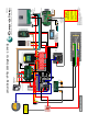
User Manual

DC LOADS +
EN3TOR-G2
Set DipSwitch to:
Standard Program
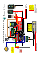
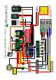
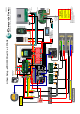
If using Dual Batteries in
Parallel or Series please
refer to:
* Parallel 12v setup drawing
* Series 24v setup drawing
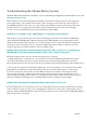
NOTE:
1.Voltage protection circuit must
be connected prior to connecting
the Battery connection Plug.
2. Never disconnect Battery
connection wires from the battery
while the lead is connected to the
EPL-ABS box.
WARNING!
EPL-ABS
14/12/2018
Battery +
Battery -
+
-
RED
BLUE
WHITE
YELLOW/GREEN
BLACK
GREEN
BLUE
BLACK
RED
WHITE
YELLOW
Inverter +
Inverter -
DC LOADS +
COMMON NEG
EPL-ABS
Voltage
Protection
Circuit
Battery
Connection
Balancer
Link N/A
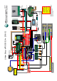
Lithium Setup - ePOWER Single 12v - 2018-G2
SR-TS-TOR-G2
TOR Output
SR-TS-TOR-G2
Wire to:
RTS Terminal
2
1
1A
10A
NOTE:
Long term storage switch.
Only turn this switch OFF once the batteries
are fully charged, the Yellow Latching Relay
is disengaged and all charging sources have
been shut down correctly.
Min 95mm Cable with a Max length of
1.5m from Battery to Connection Board.
2
Enerdrive has provided this drawing as a guide only
and installers must ensure the system is installed to the
local requirements for fuse protection and wire sizing.
If you have any questions please call;
Enerdrive on 07 3390 6900
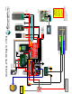
Temp Sensor
5A
Optional Cabinet Fan
Output 4 Turns on when
Temp Sensor >35
°C
EN3TOR-G2
Plug into BTS
EN3TOR-G2
Plug into BTS