INVERTER / CHARGER DC to AC true sinewave inverter programmable automatic battery charger automatic transfer switch Owner’s Manual EPC 1600-12 ePRO Combi 12V / 60Amp EPC 1800-24 ePRO Combi 24V / 35Amp EPC 2000-12 ePRO Combi 12V / 80Amp EPC 2500-24 ePRO Combi 24V / 50Amp EPC 3000-12 ePRO Combi 12V / 120Amp EPC 3500-24 ePRO Combi 24V / 70Amp
PLEASE KEEP THIS MANUAL FOR FUTURE REFERENCE For safe and optimum performance, the Enerdrive ePRO Inverter / Charger must be used properly. Carefully read and follow all instructions and guidelines in this manual and give special attention to the CAUTION and WARNING statements. Disclaimer While every precaution has been taken to ensure the accuracy of the contents of this guide, Enerdrive assumes no responsibility for errors or omissions.
Notice of Copyright Enerdrive ePRO Combi EPC 1600-12 to EPC 3500-24 inverter/charger owner’s manual © 20122014 Enerdrive . All rights reserved. No part of this document may be reproduced in any form or disclosed to third parties without the express written permission of Enerdrive Pty Ltd, Unit 11, 1029 Manly Road Tingalpa, Queensland, Australia 4173.
Table Of Contents 1. INTRODUCTION...................................................................................... 5 2. DESCRIPTION........................................................................................... 8 3. CONFIGURING THE ePRO COMBI...................................................... 10 3.1 General........................................................................................... 10 3.2 Factory default parameter settings....................................... 11 3.
1. Introduction Thank you for purchasing a Enerdrive ePRO Combi inverter/charger combination. Please read this owner’s manual for information about using the product correctly and safely. Keep this owner’s manual and all other included documentation close to the product for future reference. For the most recent manual revision, please check the downloads section on our website. The purpose of this owner’s manual is to provide explanations and procedures for operating, and configuring the ePRO Combi.
WARNING FAILURE TO FOLLOW THESE INSTRUCTIONS CAN RESULT IN DEATH OR SERIOUS INJURY When working with electrical equipment or lead acid batteries, have someone nearby in case of an emergency. Study and follow all the battery manufacturer’s specific precautions when installing, using and servicing the battery connected to the inverter. Wear eye protection and gloves. Avoid touching your eyes while using this unit. Keep fresh water and soap on hand in the event battery acid comes in contact with eyes.
WARNING SHOCK HAZARD. KEEP AWAY FROM CHILDREN! Avoid moisture. Never expose unit to snow, water, etc. Unit provides 230 VAC, treat the AC output socket the same as regular wall AC sockets at home. WARNING EXPLOSION HAZARD! DO NOT use the Enerdrive ePRO Combi in the vicinity of flammable fumes or gases (such as gas bottles or large engines). AVOID covering the ventilation openings. Always operate unit in an open and well ventilated area.
2. Description The Enerdrive ePRO Combi is an all-in-one combination of a DC to AC true sinewave inverter, an advanced multi-stage battery charger and a high speed AC transfer switch. All this is built into one compact, yet installer friendly enclosure. Besides these three main functions, there are several unique features offered as well. Some of which benefit from the strong interaction between the three main functions. The main task of the ePRO Combi is to act as an uninterruptible AC power supply (UPS).
• Fully programmable inverter, transfer switch and battery charger parameters, using the Dashboard for Windows software. • Programmable alarm relay, for optimal control of external devices like generator starting or selective load disconnection. • Freely assignable trigger input, which allows the user to control the ePRO Combi by external events. • Temperature controlled fans, to guarantee silent operation under less than full load conditions.
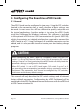
3. Configuring The Enerdrive ePRO Combi 3.1 General The ePRO Combi can be configured in two ways. Using the DIP switches located in the connection bay, a small selection of basic settings can be made. In most cases this will be sufficient to quickly setup the unit for typical applications. Another option is to setup the ePRO Combi using the Dashboard for Windows software. This software is included in the optional ePROLink to USB Communication Kit (part.
3.2 Factory Default Parameter Settings The table below shows an overview of the most relevant factory parameter settings, as stored in the ePRO Combi. These settings are based on an average application. Enerdrive cannot guarantee that these are correct for your specific application. Please check all parameters carefully, especially the battery charging voltages. Parameter Inverter frequency Value 50Hz Description Output frequency in inverter mode.
Description Enables or disables ASB. If enabled, the inverter will jump to ASB mode automatically, when the connected load power consumption drops below a user programmable level. In ASB mode the inverter pulses it’s output sinewave in order to detect when the connected load requires more power again. While running in ASB mode, the ePRO Combi itself draws significantly less current from the battery.
Parameter AC Input Current Limit Value 16.0A or 30.0A (depending on model) Description Represents the maximum continuous current that the ePRO Combi will draw from the AC input source. To assure this, the ePRO Combi will either reduce the charge current automatically, or (when enabled) will activate the AC Input Power Boost feature which will supply the additional power demand by running the inverter in parallel with the AC input source.
Description The ground switch is an internal relay that automatically connects AC output Neutral (N) to Protective Earth (PE = chassis) in inverter mode. This enables the use of a ground fault circuit interrupter (GFCI) at the AC output of the ePRO Combi. When a non-grounded (floating-) output is required, this Parameter can be disabled.
Description The default charge program AGM is compatible with typical AGM type batteries, but can be used for other types of lead-acid batteries as well. Please make sure that you always check if the ePRO Combi charge program settings, are compatible with the used battery! The AGM charge program absorption voltage is 14.3V (28.6V@24V) and the float voltage is 13.3V (26.6V@24V). Other selectable charge programs are Flooded, GEL and Custom. For further charge program information, please see chapters 3.
3.3 DIP Switch Settings Overview During step 3 of the installation guide, you can alter the factory settings of the DIP switches to change the functionality of the ePRO Combi on a few points. For additional information about the settings, see the previous chapter (3.2). The following settings can be made : Setting Description Local / External Programming ON (External) = DIP switches 2 to 7 or 9 are ignored and the ePRO Combi will always load the parameter settings as configured in Dashboard.
ASB mode ON = ASB mode on Factory setting = OFF OFF = ASB mode off Battery type / Charge program1) 5 = OFF Battery type = Flooded Factory setting 5 = OFF Factory setting 6 = ON 6 = OFF Absorption voltage = 14.4V or 28.8V Float voltage = 13.5V or 27.0V 5 = ON Battery type = GEL 6 = OFF Absorption voltage = 14.2V or 28.4V Float voltage = 13.5V or 27.0V 5 = OFF Battery type = AGM 6 = ON Absorption voltage = 14.3V or 28.6V Float voltage = 13.3V or 26.
Models : ePRO Combi 1600-1800 Bypass remote switch (Bypasses the remote switch connection when no remote switch is connected) ON = Remote switch connection terminals are bypassed Factory setting = ON OFF = remote switch connection terminals are open. A remote switch must be connected and switched ON in order to activate the ePRO Combi. The local on/off switch on the front panel always overrides the remote switch.
Models : ePRO Combi 2000-3500 only Bypass remote switch (Bypasses the remote switch connection when no remote switch is connected) ON = Remote switch connection terminals are bypassed Factory setting = ON OFF = Remote switch connection terminals are open. A remote switch must be connected and switched ON in order to activate the ePRO Combi. The local on/off switch on the front panel always overrides the remote switch.
4. General Operation 4.1 Operating the ePRO Combi The main switch on the ePRO Combi has three positions : On, Off and Charger only (see image in chapter 4.2). When switched to On, the ePRO Combi will perform all tasks automatically. It will power up in inverter mode, supplying power to the connected load. When a grid or generator is connected to the AC input, the ePRO Combi will analyse this signal.
4.2 ePRO Combi LED Indicators and Error Modes Please see the next image for an overview of all LED indicators on the ePRO Combi frontpanel, as well as the location of the main switch. The frontpanel can be divided into four sections : 1. Dual function level bar. Indicates the percentage of delivered output power in inverter mode (turns red if more than nominal output power is being delivered to the load). In charger mode, this level bar indicates the percentage of delivered charging current. 2.
‘charger on’ LED Off not charging On (green) charging On (blinking red) error (see chapter 4.2.1) On (red) charger disabled ‘inverter on’ LED Off not inverting On (green) inverting or power boosting On (blinking red) error (see chapter 4.2.
3. Charge status bar. Gives a rough indication of the charging progress, see below : LED 3a 100% full (ready) LED 3b 80% full LED 3c 50% full LED 3d empty 4. Power on, off, charger only switch. See chapter 4.1 for more explanations. 4.2.1. Error Indications When the so called mode indicator LEDs are blinking red, an error has been detected. Each mode indicator LED can either blink red individually, or combined along with one or more other mode indicator LEDs.
The ePRO Combi will mostly recover from an error mode automatically when the cause of the error has been resolved. However, when an error has occurred due to a high battery ripple voltage or an AC transfer switch over-current, the ePRO Combi needs to be switched off and on again manually (manual restart). The ePRO Combi also needs to be restarted manually, when too many battery or overload errors have occurred within a short period of time. 4.
switch or a potential free relay contact. By closing this external switch or contact, a user programmable ‘action’ will be performed. Such an action could for example be to release the AC transfer switch, temporarily disable the AC input Power Boost feature or force the ePRO Combi to switch to inverter mode. All this can be configured in ePRO Dashboard. The EPC 1600 to 1800 models are equipped with one trigger input, while the EPC 2000 to 3500 models are equipped with two trigger inputs. 4.
5. Charger Operation 5.1 Charge Programs All standard selectable charge programs (using DIP switches 5 and 6), perform a four stage IUoUoP charging process comprising of a “Bulk”, an “Absorption”, a “Float” and a “Pulse” stage.
In the Bulk stage, the charger delivers full output current and typically returns approximately 80% of charge back into the battery once the absorption voltage is reached. During this stage, the battery empty and battery 50% full indicators will be lit depending on the Bulk charge progress. When the absorption voltage has been reached, the Absorption stage will be entered and the battery 80% full indicator will be lit. This stage will return the final 20% of charge to the battery.
at 12V chargers and -60mV/°C at 24V chargers). This way, overcharging is prevented which prolongs your battery’s lifetime. When the standard selectable charging programs do not satisfy your requirements, or when different voltage- and current levels are needed, you can edit or create your own charge programs using ePRO Dashboard. Up to 8 different stages can be linked together and all individual stages can be configured extensively.
5.2 Equalizing a Flooded Battery If you are using a flooded lead acid battery, an occasional equalization charge cycle may be recommended by the manufacturer. This might also be true when the flooded battery has been very deeply discharged or often charged inadequately. During equalization, the battery will be charged up to 15.5V (or 31V for 24V models) at a reduced output current level.
Since equalization is only allowed for flooded (wet-) lead acid batteries, the ePRO Combi will only allow this function to be available when the “Flooded” charging program is selected (see chapter 3.3). Besides this, the charger also needs to have a full charge cycle completed and must operate in the Float stage.
The ePRO Combi will allow a maximum equalization time of 2 hours before it automatically jumps back to the Float stage. If the specific gravity of each cell does not match the battery manufacturer’s specifications yet, you can initiate a new 2 hours equalization cycle by pressing the push-button for 3 seconds again. Always keep on checking the specific gravity of each cell repeatedly during the equalization process.
6. Troubleshooting Guide Please see the table below if you experience any problems with the ePRO Combi and/or the installation. Problem Possible cause Remedy ePRO Combi is not working at all. Main switch in Off (0) position. Push the power switch in the ‘I’ or ‘II’ position. Remote switch or Universal Remote Control have deactivated the ePRO Combi. Activate the ePRO Combi remotely or check DIP switch 8 or 10 for correct setting.
The battery is not being charged up to it’s maximum capacity. Charge current is too low. Incorrect absorption charge voltage setting. Check DIP switch 5 and 6 for correct settings. Or adjust the absorption voltage using ePRO Dashboard. Incorrect charge current setting. Adjust the charge current using the Universal Remote Control or ePRO Dashboard. Typically, the charge current should be set to 10%-20% of the total battery capacity Too much voltage loss in battery cables and/or connections.
Mode indicator LEDs ‘inverter on’, ‘charger on’ and ‘AC in’ are blinking red once per second (battery error). Battery voltage is too low (< 8V@12V or <16V@24V). Battery is damaged, replace it. Or battery has been discharged too extremely, let it slowly recover to above 8.5V so that the transfer switch and charger can startup to recharge the battery. Battery voltage is too high (>16.5V or >33V@24V). Check the DC system for an external source that pushes the battery voltage too high.
Connected AC output load causes a short circuit. Make sure that the AC output load is not defective. Check if the AC output wiring and connections are not creating a short circuit. Connected AC output load Try to power-up connected causes a too large inrush current. equipment successively, and not simultaneously. Otherwise stop using the connected load, it’s not suitable to power it with this inverter. Mode indicator LEDs ‘inverter on’ and ‘charger on’ are blinking red three times per second.
Mode indicator LED ‘AC in’ blinks red once per second. AC input signal is present but not within required voltage and frequency borders. Make sure that the AC input voltage falls within 185V270V and 45Hz-65Hz. All mode indicator LEDs ‘inverter on’, ‘charger on’ and ‘AC in’ are blinking red twice per second (manual restart needed) Maximum AC transfer switch current has been exceeded. Reduce the AC output load Mode indicator LED ‘inverter on’ or ‘charger on’ or ‘AC in’ is red continuously.
All mode indicator LEDs ‘inverter on’, ‘charger on’ and ‘AC in’ are blinking red four times. Device or connection fault. Mode indicator LED ‘charger on’ blinks five times. Charge program error. ePRO Combi is defective, return for service. External AC source is connected to the AC output instead of the AC input. User has selected an empty or invalid charge program (‘custom’ charge program is empty from factory).
7. Technical Specifications EPC1600-12-60 / EPC1800-24-35 Parameter EPC1600-12-60 EPC1800-24-35 Pnom 1300W 1400W P10minutes 1600W 1800W Psurge 2500W 3000W Inverter stage Output power 1) Output voltage / frequency 230Vac ± 2% / 50Hz ± 0.05% Output waveform True sinewave (THD < 5% 1) @ Pnom) Input voltage (± 3% tolerance): Nominal Range Maximum efficiency No load power consumption [ASB] 3) 12V 24V 10.5 – 16Vdc 21 – 32Vdc 92% 94% < 10W [2.0W] < 12W [2.
Enclosure body size 351 x 210 x 114mm Total weight 10.7kg Protection class / Op. temp. / Storage temp. Standards IP21 / -20°C .. +50°C / -40°C .. +80°C Complies with IEC 60335-2-29 including Australian deviations. Note : the given specifications are subject to change without notice. 1. Measured with resistive load. Power ratings are subject to a tolerance of 10% and are decreasing as temperature rises with a rate of approx. 1.2%/°C starting from 25°C. 2. Undervoltage limit is dynamic.
EPC2000-12-80 / EPC2500-24-50 Parameter EPC2000-12-80 EPC2500-24-50 Inverter stage Output power 1) Pnom 1800W 2000W P10minutes 2100W 2500W Psurge 4000W 5500W Output voltage / frequency 230Vac ± 2% / 50Hz ± 0.05% Output waveform True sinewave (THD < 5% 1) @ Pnom) Input voltage (± 3% tolerance): Nominal Range Maximum efficiency No load power consumption [ASB] 3) 12V 24V 10.5 – 16Vdc 21 – 32Vdc 92% 93% < 20W [3.5W] < 20W [4.
Total weight 18.5kg Protection class / Op. temp. / Storage temp. Standards IP21 / -20°C .. +50°C / -40°C .. +80°C Complies with IEC 60335-2-29 including Australian deviations. Note : the given specifications are subject to change without notice. 1. Measured with resistive load. Power ratings are subject to a tolerance of 10% and are decreasing as temperature rises with a rate of approx. 1.2%/°C starting from 25°C. 2. Undervoltage limit is dynamic.
EPC3000-12-120 / EPC3500-24-70 Parameter EPC3000-12-120 EPC3500-24-70 Inverter stage Output power 1) Pnom 2600W 2800W P10minutes 3200W 3800W Psurge 5000W 6500W Output voltage / frequency 230Vac ± 2% / 50Hz ± 0.05% Output waveform True sinewave (THD < 5% 1) @ Pnom) Input voltage (± 3% tolerance): Nominal Range Maximum efficiency No load power consumption [ASB] 3) 12V 24V 10.5 – 16Vdc 21 – 32Vdc 92% 93% < 20W [3.5W] < 20W [4.
Total weight 19.0kg Protection class / Op. temp. / Storage temp. Standards IP21 / -20°C .. +50°C / -40°C .. +80°C Complies with IEC 60335-2-29 including Australian deviations. Note : the given specifications are subject to change without notice. 1. Measured with resistive load. Power ratings are subject to a tolerance of 10% and are decreasing as temperature rises with a rate of approx. 1.2%/°C starting from 25°C. 2. Undervoltage limit is dynamic.
8. Warranty TWO YEAR LIMITED WARRANTY Our goods come with guarantees that cannot be excluded under the Australian Consumer Law. You are entitled to a replacement or refund for a major failure and for compensation for any other reasonably foreseeable loss or damage. You are also entitled to have the goods repaired or replaced if the goods fail to be of acceptable quality and the failure does not amount to a major failure.
to Enerdrive within 30 days of the date of purchase will be replaced free of charge. If such a unit is returned more than 30 days but less than two years from the purchase date, Enerdrive will repair the unit or, at its option, replace it, free of charge. If the unit is repaired, new or reconditioned replacement parts may be used, at manufacturer’s option. A unit may be replaced with a new or reconditioned unit of the same or comparable design.
Page 46 Enerdrive ePRO Inverter / Charger Owners Manual
Enerdrive ePRO Inverter / Charger Owners Manual Page 47
Page 48 Enerdrive ePRO Inverter / Charger Owners Manual