
Installation guide


6
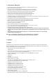
3.2 Basic Configuration of Fastrax III Dome Camera System
Figure 4 - Basic installation diagram
The dome camera must be installed by qualified service personnel in accordance with all local and federal electrical and building codes.
The system should be installed according to Figures 4 through 9.
Power
24VAC
STP AWG #24
Sensor
Alarm input
up to 8
Siren
Light
Alarm output
up to 4
BNC
Alarm output
1 ~ 2
Alarm input
1 ~ 4
Power
24VAC
Dome1+
Dome1–
Alarm output
3 ~ 4
Alarm input
5 ~ 8
Monitor
RS-485
Half Duplex mode: RX+(TX+), RX–(TX–)
RS-422
Simplex mode: (RX+), (RX–)
Duplex mode: RX+(TX+), RX–(TX–), (RX+), (RX–)
Rear
Master Keyboard controller
J-Box Dome
RS485(+) DOME1 + RX+(TX+)
RS485(-) DOME1 - RX-(TX-)
Slave Keyboard controller
Rear