
Product Manual

- 04 -
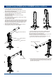
Install Crane E1000 series & E2000 series-continue
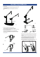
2. Put the mast weldment(#3) into the base(#1) fig.11.
The mast weldment can rotate 360° in the base(#1).
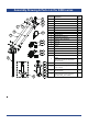
Refer to Assembly Drawing and Part List on page x for E1000
series and page x for E2000 series.
3. Fasten the upper bracket weldment(#10-RC1000, #9-E2000) to
the mast weldment(#3) with clevis pins(#9-E1000,
#10-E2000) provided fig.12.
Secure the clevis pins in place with lynch pins provided
(#7-E1000,#11-E2000).
Refer to Assembly drawing & parts list for E1000 series on page
10, for E2000 series on page 11.
4. Assemble Ratchet Jack(#5)
Adjust the ratchet jack to the greatest length and fit it to the upper
boom weldment with the the upper boom weldment(#10-RC1000;
#9-E2000) at horizontal postion by applying clevis pins to secure
two ends of the ratchet jack to the mast weldment(#3) and the
upper boom weldment respectively fig.13.
5. Fit the lever(#6) to the low end of the upper bracket weldment
using cotter pin and lynch pin to secure in place.
Fig.12Fig.11
Fig.14
Fig.13
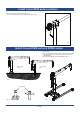
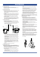
6. Slide the telescopic boom(#12-E
1000; #13-E2000) into the
upper bracket weldment(#10-E1000; #9-E2000) and secure in
place with clevis pin lynch pin provided fig.14.
There are 3 positions for the telescopic boom in the upper bracket
weldment to regulate the boom extended length.
7. Fit the pulley assembly(#17-E1000, #18-E2000) to the teles-
copic boom with axis pin and cotter pin provided.
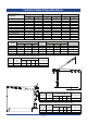
Lever
Pulley
Winch
Upper bracket weldment
Mast weldment
Ratchet Jack
Telescopic boom weldment
Fig.15
8. Secure the winch to the mounting plate using fasteners provided.
Lead the steel cable assembly through between the pulley and
the stop pin and fit to the winch drum as instructed in the winch
operation manual provided.
Cable assembly