DAVIT CRANES Instructions & Operation Manual ISO 9001:2015 IATF 16949:2016 TO PREVENT SERIOUS INJURY, READ AND UNDERSTAND ALL WARNINGS AND INSTRUCTIONS BEFORE USE. Due to continuing improvements,actual product may differ slightly from the product described herein.
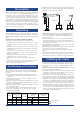
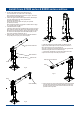
6) Adjust the boom to proper position so that the load hook is centered over the load. Avoid side pulls which could damage the crane or cause the load to tip. Fig.1 Description Davit cranes are perfect for permanent or portable installation. These cranes consist of an angled beam which pivots over a vertical axis. They can have fixed or adjustable booms, and are available in portable as well as stationary units. Davit cranes incorporate a hand operated and cable assembly for load handling.
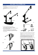
Assemble Crane E500series 1. Mounting Base There are three ways to mount the base. One is to mount the base on the ground(pedestal) or under the ground(socket) fig.2 , and on Roll Base fig.3. After the base is installed, insert Fixing Bush(#1-1) as sown in fig.4. Base installed on roll base Base installed flush Base installed upright Fig.3 Fig.2 Fixing Bush 2. Put the mast weldment(#2) into the base(#1). The mast weldment can rotate 360° in the base(#1).
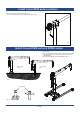
Install Crane E500 series-continue 7. Mount the winch using hardware provided. Fig.7 For winch installation refer to winch operation manual provided. Fig.7 Install Crane E1000 series & E2000 series 1. Mounting Base There are three ways to mount the base. One is to mount the base on the ground(pedestal) or under the ground(socket) fig.8 , and on Roll Base fig.9. After the base is installed, insert Fixing Bush(#2) fig.10. Base installed upright Base installed flush Fig.8 Fixing Bush Fig.10 Fig.
Install Crane E1000 series & E2000 series-continue 2. Put the mast weldment(#3) into the base(#1) fig.11. The mast weldment can rotate 360° in the base(#1). Refer to Assembly Drawing and Part List on page x for E1000 series and page x for E2000 series. 3. Fasten the upper bracket weldment(#10-RC1000, #9-E2000) to the mast weldment(#3) with clevis pins(#9-E1000, #10-E2000) provided fig.12. Secure the clevis pins in place with lynch pins provided (#7-E1000,#11-E2000).
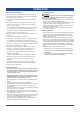
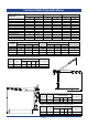
OPERATION A. Cautions before operation C. Attaching the load WARNING 1. The force required to lift the load must not exceed the load rating of the crane. Consider the total force required to lift the load, not the weight of the load. 2. This equipment can not develop forces that will exceed the load rating. 3. Performance ratings of the equipment are affected by the position of the boom. See the performance characteristics Table 4, Table 5, Table 6.
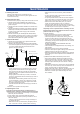
MAINTENANCE A. Cleaning the crane • Make sure the load moves smoothly, without hesitation or strain. • On hand operated models, make sure the winch handle rotates freely in both directions. • On power operated models, make sure the winch responds to the control device. It must rotate as shown on the control labels, and it must turn off when you release the control. • Make sure the boom rotates freely when you push the handle, and remains stationary when you release it. • Check the brake.
MAINTENANCE-continue Wire Strand • Note the location and concentration of broken wires. Replace wire rope if more than 6 wires are broken in one lay, or more than 3 wires are broken in one strand in one lay. See figure 19 • Check the anchor holes in the drum and the surrounding area for signs of wear or distortion. one lay Fig.19 3) PLACE 100 POUNDS of tension on the wire rope • Measure the diameter of the wire rope, especially in areas where wear is noticeable.
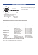
Technical Data & Specifications Table 2-weight chart E500 series Component Pedestal Socket Base Roll Base Mast Upper Bracket Weldment Telescopic Boom Weldment Ratchet Jack(Lever included) Winch RBW1500-05 Winch RBW1000SS Winch RBW2500-16 Winch RWP2000-02 Winch RBW3500-03 E1000 series E2000 series kgs lbs kgs lbs kgs lbs 8.1 8.1 26.5 13.7 12.0 9.6 / 3.4 6.0 / / / 17.8 17.8 58.4 30.2 26.5 21.2 / 7.5 13.2 / / / 22.0 19.0 112.0 25.6 17.5 10.2 8.6 / / 6.9 16.6 / 48.5 41.9 247.0 56.4 38.6 22.5 19.
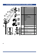
Assembly Drawing & Parts List for E500 series 7 5 8 9 10 11 6 4 12 3 Part N0. Description 1 Base 1 1-1 Mast Bush 1 1-2 Base Weldment 1 1-3 Bolt M12x110 1 1-4 Spring Washer M12 1 1-5 Nut M12 1 1-6 Roller 2 2 Mast Weldment 1 3 Upper Bracket Weldment 1 4 Telescopic Boom Weldment 1 13-1 5 Clevis Pin 3 13-2 6 Cotter Pin 3 7 Axis Pin 1 8 Stop Pin 6 x 50 1 1 14-1 9 Pulley Assembly 10 Hair Cotter Pin 1 14-2 11 Cotter Pin 3.
Assembly Drawing & Parts List for E1000 series 13 14 17 12 15 16 11 19-1 10 9 18-1 8 19-2 7 18-2 6 5 19-3 18-3 4 2 3 20 1-2 1-1 Part N0. 1-1 1-2 2 3 4 5 6 7 8 9 10 11 12 Description Pedestal Base Socket Base Mast Bush Mast Weldment Pin Ø23x85 Ratchet Jack Assembly Lever Lynch Pin Clevis Pin Clevis Pin Upper Bracket Weldment Clevis Pin Telescopic Boom Weldment Qty Part N0.
Assembly Drawing & Parts List for E2000 series 18 17 16 13 14 15 11 12 9 8 20-1 7 19-1 10 6 5 19-2 4 20-2 3 21 2 1-2 1-1 Part N0. Description Qty Part N0. Description Qty 1-1 Base Weldment for upright 1 13 Telescopic Boom Weldment 1 1-2 Base Weldment for flush 1 14 Cotter Pin 3.2x28 1 2 Fixing Bush 1 15 Cotter Pin 1.