
Operating Instructions


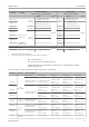


Table Of Contents
- Table of contents
- 1 About this document
- 2 Basic safety instructions
- 3 Incoming acceptance and product identification
- 4 Installation
- 5 Electrical connection
- 6 Operation options
- 7 System integration
- 8 Commissioning
- 9 Diagnostics and troubleshooting
- 10 Maintenance
- 11 Repair
- 12 Accessories
- 13 Technical data
- 14 Operating menu and parameter description

Technical data iTEMP TMT72
56 Endress+Hauser
Measuring category Measuring category II as per IEC 61010-1. The measuring category is provided for
measuring on power circuits that are directly connected electrically with the low-voltage
network.
Degree of contamination Pollution degree 2 as per IEC 61010-1.
13.6 Mechanical construction
Design, dimensions Dimensions in mm (in)
Head transmitter
24.1
(0.95)
33 (1.3)
!
44 (1.73)
!
7 (0.28)
!
5 (0.2)
B
C
A
A0036303
14 Version with screw terminals
A Spring travel L ≥ 5 mm (not for US - M4 securing screws)
B Mounting elements for attachable measured value display TID10
C Service interface for connecting measured value display or configuration tool
Field housing
All field housings have an internal geometry in accordance with DIN EN 50446, form B
(flat face). Cable glands in the diagrams: M20x1.5
Maximum ambient temperatures for cable glands
Type Temperature range
Polyamide cable gland ½" NPT, M20x1.5 (non-Ex) –40 to +100 °C (–40 to 212 °F)
Polyamide cable gland M20x1.5 (for dust ignition-proof area) –20 to +95 °C (–4 to 203 °F)
Brass cable gland ½" NPT, M20x1.5 (for dust ignition-proof area) –20 to +130 °C (–4 to +266 °F)
TA30A Specification
107.5 (4.23)
68.5 (2.7)
28
(1.1)
78 (3.1)
15.5 (0.6)
A0009820
• Two cable entries
• Temperature: –50 to +150 °C (–58 to +302 °F) without cable
gland
• Material: aluminum, polyester powder coated
Seals: silicone
• Cable entry glands: 1/2" NPT and M20x1.5
• Color of head: blue, RAL 5012
• Color of cap: gray, RAL 7035
• Weight: 330 g (11.64 oz)