
Operating Instructions


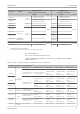


Table Of Contents
- Table of contents
- 1 About this document
- 2 Basic safety instructions
- 3 Incoming acceptance and product identification
- 4 Installation
- 5 Electrical connection
- 6 Operation options
- 7 System integration
- 8 Commissioning
- 9 Diagnostics and troubleshooting
- 10 Maintenance
- 11 Repair
- 12 Accessories
- 13 Technical data
- 14 Operating menu and parameter description

iTEMP TMT72 Technical data
Endress+Hauser 55
Analog output long-term drift
D/A long-term drift
1)
(±)
after 1 month after 6 months after 1 year after 3 years after 5 years
0.018% 0.026% 0.030% 0.036% 0.038%
1) Percentages based on the configured span of the analog output signal.
Influence of the reference
junction
Pt100 DIN IEC 60751 Cl. B (internal reference junction with thermocouples TC)
If an external 2-wire RTD is used for the reference junction measurement, the measured
error caused by the transmitter is < 0.5 °C (0.9 °F). The measured error of the sensor
element also needs to be added.
13.5 Environment
Ambient temperature
range
–40 to +85 °C (–40 to +185 °F), for hazardous areas see Ex documentation
Storage temperature Head transmitter: –50 to +100 °C (–58 to +212 °F)
Altitude Up to 4000 m (4374.5 yards) above mean sea level as per IEC 61010-1, CAN/CSA C22.2
No. 61010-1
Humidity • Condensation as per IEC 60 068-2-33:
Head transmitter permitted
• Max. rel. humidity: 95% as per IEC 60068-2-30
Climate class Head transmitter: climate class C1 as per EN 60654-1
Degree of protection • Head transmitter with screw terminals: IP 00. In installed state, depends on the terminal
head or field housing used.
• When installing in field housing TA30A, TA30D or TA30H: IP 66/68 (NEMA Type 4x
encl.)
Shock and vibration
resistance
Vibration resistance as per DNVGL-CG-0339 : 2015 and DIN EN 60068-2-27
Head transmitter: 2 to 100 Hz at 4g (increased vibration stress)
Shock resistance as per KTA 3505 (section 5.8.4 Shock test)
Electromagnetic
compatibility (EMC)
CE compliance
Electromagnetic compatibility in accordance with all the relevant requirements of the
IEC/EN 61326 series and NAMUR Recommendation EMC (NE21). For details, refer to the
Declaration of Conformity. All tests were passed both with and without ongoing digital
HART
®
communication.
Maximum measured error <1% of measuring range.
Interference immunity as per IEC/EN 61326 series, industrial requirements
Interference emission as per IEC/EN 61326 series, Class B equipment