
Operating Instructions
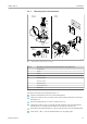


Table Of Contents
- Table of contents
- 1 About this document
- 2 Basic safety instructions
- 3 Incoming acceptance and product identification
- 4 Installation
- 5 Electrical connection
- 6 Operation options
- 7 System integration
- 8 Commissioning
- 9 Diagnostics and troubleshooting
- 10 Maintenance
- 11 Repair
- 12 Accessories
- 13 Technical data
- 14 Operating menu and parameter description

iTEMP TMT72 Operation options
Endress+Hauser 19
Item no. Function Description
1 Displays the TAG TAG, 32 characters long.
2 'Communication' symbol The communication symbol appears when read and write-accessing via
the fieldbus protocol.
3 Unit display Unit display for the measured value displayed.
4 Measured value display Displays the current measured value.
5 Value/channel display
DT, PV, I, %
e.g. PV for a measured value from channel 1 or DT for the device
temperature
6 'Configuration locked'
symbol
The 'configuration locked' symbol appears when configuration is locked
via the hardware.
7 Status signals
Symbols Meaning
Error message "Failure detected"
An operating error has occurred. The measured value is no longer valid.
The display alternates between the error message and "- - - -" (no valid
measured value present), see "Diagnostics events" section→ 37.
Detailed information on the error messages can be found in the
Operating Instructions.
"Service mode"
The device is in service mode (e.g. during a simulation).
"Out of specification"
The device is being operated outside its technical specifications (e.g.
during warm-up or cleaning processes).
"Maintenance required"
Maintenance is required. The measured value is still valid.
The display alternates between the measured value and the status
message.
Local operation
You can make various hardware settings using miniature switches (DIP switches) on the
rear of the optional display.
The user has the option of ordering the display with the head transmitter, or as an
accessory for subsequent mounting. → 42
NOTICE
‣
ESD - electrostatic discharge. Protect the terminals from electrostatic discharge.
Failure to observe this may result in the destruction or malfunction of parts of the
electronics.
ON
OFF
1
2
4
8
16
32
64
HW
SW
ADDR ACTIVE
SIM
WRITE LOCK
DISPL. 180°
1
2
3
A0014562
12 Hardware settings via DIP switches
1: Connection to head transmitter
2: DIP switches (1 - 64, SW/HW, ADDR and SIM = simulation
mode) no function for this head transmitter
3: DIP switch (WRITE LOCK = write protection; DISPL. 180° =
switch, turn the display monitor 180°)
Procedure for setting the DIP switch:
1. Open the cover of the terminal head or field housing.
2. Remove the attached display from the head transmitter.