
Operating Instructions
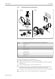


Table Of Contents
- Table of contents
- 1 About this document
- 2 Basic safety instructions
- 3 Incoming acceptance and product identification
- 4 Installation
- 5 Electrical connection
- 6 Operation options
- 7 System integration
- 8 Commissioning
- 9 Diagnostics and troubleshooting
- 10 Maintenance
- 11 Repair
- 12 Accessories
- 13 Technical data
- 14 Operating menu and parameter description

iTEMP TMT72 Electrical connection
Endress+Hauser 17
-
.
1
2
3
4
A0014463
8
Shielding and grounding the signal cable at one end with HART
®
communication
1 Optional grounding of the field device, isolated from cable shielding
2 Grounding of the cable shield at one end
3 Supply unit
4
Grounding point for HART
®
communication cable shield
5.6 Post-connection check
Device condition and specifications Notes
Is the device or cable undamaged (visual check)? --
Electrical connection Notes
Does the supply voltage match the specifications on
the nameplate?
• Head transmitter: U = e.g. 10 to 36 V
DC
• Other values apply in the hazardous area, see the
corresponding Ex Safety Instructions (XA).
Do the cables have adequate strain relief? --
Are the power supply and signal cables correctly
connected?
→ 15
Are all the screw terminals well tightened? --
Are all the cable entries installed, tightened and
sealed?
--
Are all housing covers installed and firmly tightened? --