
Operating Instructions
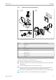


Table Of Contents
- Table of contents
- 1 About this document
- 2 Basic safety instructions
- 3 Incoming acceptance and product identification
- 4 Installation
- 5 Electrical connection
- 6 Operation options
- 7 System integration
- 8 Commissioning
- 9 Diagnostics and troubleshooting
- 10 Maintenance
- 11 Repair
- 12 Accessories
- 13 Technical data
- 14 Operating menu and parameter description

Electrical connection iTEMP TMT72
16 Endress+Hauser
5.4 Connecting the transmitter
Cable specification
• A normal device cable suffices if only the analog signal is used.
• A shielded cable is recommended for HART
®
communication. Observe grounding
concept of the plant.
Please also observe the general procedure on → 15.
1 2 3
4
2-
1+
2-
1+
2- 1+
5
6
7
4
5
7
A0017841
7 Connecting the signal cables and power supply
1 Head transmitter installed in field housing
2 Head transmitter installed in terminal head
3 DIN rail transmitter mounted on DIN rail
4
Terminals for HART
®
protocol and power supply
5 Internal ground connection
6 External ground connection
7
Shielded signal cable (recommended for HART
®
protocol)
• The terminals for signal cable connection (1+ and 2-) are protected against reverse
polarity.
• Conductor cross-section:
Max. 2.5 mm
2
for screw terminals
5.5 Special connection instructions
Shielding and grounding
The specifications of the HART
®
FieldComm Group must be observed when installing a
HART® transmitter.