
Operating Instructions
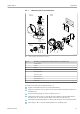


Table Of Contents
- Table of contents
- 1 About this document
- 2 Basic safety instructions
- 3 Incoming acceptance and product identification
- 4 Installation
- 5 Electrical connection
- 6 Operation options
- 7 System integration
- 8 Commissioning
- 9 Diagnostics and troubleshooting
- 10 Maintenance
- 11 Repair
- 12 Accessories
- 13 Technical data
- 14 Operating menu and parameter description

iTEMP TMT72 Electrical connection
Endress+Hauser 15
5 Electrical connection
L
CAUTION
‣
Switch off the power supply before installing or connecting the device. Failure to
observe this may result in the destruction of parts of the electronics.
‣
Do not occupy the display connection. An incorrect connection can destroy the
electronics.
5.1 Connection conditions
Proceed as follows to wire a mounted head transmitter:
1. Open the cable gland and the housing cover on the terminal head or the field
housing.
2. Feed the cables through the opening in the cable gland.
3. Connect the cables as shown in → 15.
4. Tighten the cable gland again and close the housing cover.
In order to avoid connection errors always follow the instructions in the post-connection
check section before commissioning!
5.2 Quick wiring guide
6
5
4
3
1+
2-
6
5
4
3
Sensor input
Supply
voltage/
bus connection
Display connection/
CDI interface
TC, mV
RTD, Ω 4-, 3- and 2-wire:
white
white
red
red
A0038010-EN
6 Terminal assignment of head transmitter
A minimum load of 250 Ω is required in the signal circuit in order to operate the HART
®
transmitter via the HART
®
protocol (terminals 1 and 2).
In the event of a thermocouple (TC) measurement, a 2-wire RTD can be connected to
measure the reference junction temperature. This is connected to terminals 4 and 6.
NOTICE
‣
ESD - electrostatic discharge. Protect the terminals from electrostatic discharge.
Failure to observe this may result in the destruction or malfunction of parts of the
electronics.
5.3 Connecting the sensor cables
Terminal assignment of the sensor connections→ 6, 15.