
Operating Instructions


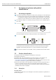
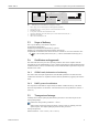
Table Of Contents
- Table of contents
- 1 About this document
- 2 Basic safety instructions
- 3 Incoming acceptance and product identification
- 4 Installation
- 5 Electrical connection
- 6 Operation options
- 7 System integration
- 8 Commissioning
- 9 Diagnostics and troubleshooting
- 10 Maintenance
- 11 Repair
- 12 Accessories
- 13 Technical data
- 14 Operating menu and parameter description

Installation iTEMP TMT72
10 Endress+Hauser
4 Installation
4.1 Installation conditions
4.1.1 Dimensions
The dimensions of the device are provided in the "Technical data" section → 56.
4.1.2 Mounting location
Head transmitter:
– In the terminal head, flat face, as per DIN EN 50446, direct mounting on insert with
cable entry (middle hole 7 mm)
– In the field housing, separated from the process→ 42
It is also possible to mount the head transmitter on a DIN rail as per IEC 60715 using
the DIN rail clip → 42accessory.
Information about the conditions (such as the ambient temperature, degree of protection,
climate class etc.) that must be present at the installation point so that the device can be
mounted correctly is provided in the "Technical data" section→ 55.
When using in hazardous areas, the limit values of the certificates and approvals must be
observed (see Ex Safety Instructions).
4.2 Installation
A suitable screwdriver is required to mount the head transmitter:
• Maximum torque for mounting screws = 1 Nm (¾ pound-feet), screwdriver: Pozidriv Z2
• Maximum torque for screw terminals = 0.35 Nm (¼ pound-feet), screwdriver: Pozidriv
Z1