
Instructions
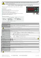

EPV242-E-150419
4. / 4
E-mail : info@suran-elektronik.de
Internet : www.suran-elektronik.de
Tel.: +49 (0)7451 / 625 617
Fax: +49 (0)7451 / 625 0650
SURAN Industrieelektronik
Dettinger Str. 9 / D-72160 Horb a.N
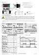
* MODBUS CONNECTION DIAGRAM
120 Ohm
Master
Slave - 1
Up to 127 slave devices can be controlled.
Slave - 2
Slave - 127
A
B
A
B
A
B
A
B
Termination should be accomplished by attaching 120 Ohm
resistors to the start and at the end of the communication
line.
*Applies to devices with Modbus function.
0001d
0002d
0003d
0004d
0005d
0006d
0007d
0009d
0010d
0011d
0012d
0x0001
0x0002
0x0003
0x0004
0x0005
0x0006
0x0007
0x0009
0x000A
0x000B
0x000C
word
word
word
word
word
word
word
word
word
word
word
The upper limit of the hysteresis value
Delay time for the upper limit alarm
The lower limit of the setpoint
The lower limit of the hysteresis value
Delay time for the lower limit alarm
Input type selection
Measurement method ( =0 AC 1 DC 2 ACDC, = , = )
Decimal point. (0=X, 1=X.X, 2=X.XX, 3=X.XXX)
Baudrate (0=Off;1=1200;2=2400; 3=4800; 4=9600; 5=19200
6= 38400; 7= 57600; 8= 115200)
dlyU
L0Ll
HY5L
dLyl
UPLL
1tYP
typE
dpnt
OPTN
aDr5
BAUD
100
500.0
1,0
1,0
0
no
aCdC
0.0
4
1
oFF
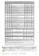
Input Register
Addresses
Decimal
Hex
Data
Type
Data Content
Parameter
Name
Read/Write Permission
0000d
0x0000
word
Measured voltage value
--
Only Readable
INPUT REGISTERS FOR R EXTENSION DEVICES
Discrete Input
Addresses
Decimal
Hex
Data
Type
Data Content
Parameter
Name
0000d
0x0000
Bit
Relay output state (0= ; 1= )OFF ON
--
DISCRETE INPUTS FOR R EXTENSION DEVICES
Coil Addresses
Decimal
Hex
Data
Type
Data Content
Parameter
Name
Read/Write
Permission
0000d
0x0000
Bit
Alarm output state (0= ; 1= )no nc
0tYP
COILS FOR R EXTENSION DEVICES
Status
Value
Readable/Writable
Readable/Writable
Readable/Writable
Readable/Writable
Readable/Writable
Readable/Writable
Readable/Writable
Readable/Writable
Readable/Writable
Readable/Writable
Readable/Writable
Only Readable
Read/Write Permission
Readable/Writable
0000d
0003d
0004d
0005d
0006d
0007d
0x0000
0x0003
0x0004
0x0005
0x0006
0x0007
word
word
word
word
word
word
Measurement method ( =0 AC 1 DC 2 ACDC, = , = )
Decimal point. (0=X.XX,1=X.X,2=X)
Baudrate (0=Off;1=1200;2=2400; 3=4800; 4=9600; 5=19200
6= 38400; 7= 57600; 8= 115200)
typE
dpnt
OPTN
aDr5
BAUD
100
aCdC
0.000
4
1
9600
Readable/Writable
Readable/Writable
Readable/Writable
Readable/Writable
Readable/Writable
Readable/Writable
*Holding Register Parameter Table (No Relay Models)
Device address for RS485 network connection.
Adjustable between 1-247.
Sampling time of the measurement value. If 1 is selected, it is
250ms. If 2 is selected, it is 500ms. If 3 is selected, it is 750ms.
If 4 is selected, it is 1 second.
Sampling time of the measurement value
Device address for RS485 network connection.
Adjustable between 1-247.
* Coil and Discrete input parameters are not available in the devices those have no relay
Holding Register
Addresses
Decimal
Hex
Data
Type
Data Content
Parameter
Name
Read/Write
Permission
Status
Value
0000d
0x0000
word
Voltage Conversion Rate
Readable/Writable
u.t.r.r
HOLDING REGISTERS FOR R EXTENSION DEVICES
ENDA EPV242 DIGITAL VOLTMETER MODBUS PROTOCOL ADDRESS MAP
0013d
0x000D
word
Readable/Writable
Alarm output status
0tyP
0
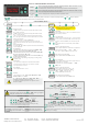
Note 1 : menu parameters can be used as “Holding Register” or “Coil.0tyP
Note 2 : Received "ModBus input register value" is multiplying by 1000 (based on ) and mV value reached.
For example ;
if modbus value is 2842, (for = 2 ( )) 28.42x1000 = 28420 mV, ie 28.42V
if modbus value is 2842, (for = 3 ( )) 2.842x1000 = 2842 mV, ie 2.842V
d.pnt
d.pnt 0.00
d.pnt 0.000
0008d
0x0008
word
Readable/Writable
u.t.r.r
The upper limit of the setpoint
HY5U
0,0
Input type selection
1tYP
Voltage Conversion Rate
u.t.r.r
Readable/Writable
u.t.r.r
0001d
0x0001
word
no