
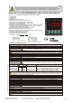
User manual

4 digits 7 segment red LED display
( 4 ),( 5 ),( 6 ),( 7 ) Key pad
( 3 ) Digital display
5) Shows minimum measured value. (Run mode)
Decreases value or adjusts parameter. (Programlama modu)
6) Shows alarm set value. (Run mode)
Menu selection key. (Programming mode)
7) Shows out set value. (Run mode)
Parameter adjustment key. (Programming mode)
14.2mm
Mikro switch
Character height
3mm bright red LED
( 1 ),( 2 ) Out and Alarm LED
TERMS
3) Shows measurement value, measurement unit and maximum and
minimum measured values. (Run mode)
Shows name, value and unit of parameters. (Programming mode)
4) Shows maximum measured value. (Run mode)
Increases value or adjusts parameter. (Programming mode)
1) Shows out status.
2) Shows alarm status.
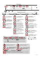
CONNECTION DIAGRAM
ENDA EI7412 is intended for installation in control panels. Make sure that the device is used only for intended purpose. The shielding must be
grounded on the instrument side. During an installation, all of the cables that are connected to the device must be free of energy. The device
must be protected against inadmissible humidity, vibrations, severe soiling and make sure that the operation temperature is not exceeded. All
input and output lines that are not connected to the supply network must be laid out as shielded and twisted cables. These cables should not be
close to the power cables or components. The installation and electrical connections must be carried on by a qualified staff and must be
according to the relevant locally applicable regulations.
1) Mains supply cords shall meet the requirements of IEC 60227 or IEC 60245.
2) In accordance with the safety regulations, the power supply switch shall bring the identification of the relevant instrument and it
should be easily accessible by the operator.
Note :
8
7
184-253V AC
50/60Hz 7VA
230V AC
Supply
Switch
Cable size: 1,5mm²
Fuse
F 100 mA
250V AC
Neutral
Line
SUPPLY :
NOTE :
Fuse should
be connected
Holding screw
0.4-0.5Nm
Equipment is protected throughout
by DOUBLE INSULATION.
PROGRAMMABLE INDICATOR
ENDA
EI 7412
OSET
SET
MAX
ASET
OUT
ALR
MIN
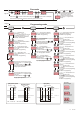
Panel cut-out
75mm
84mm
68 mm
+0.7
68 mm
+0.7
Depth
97mm
2
2
Note 1) While panel mounting, additional distance required
for connection cables should be considered.
2) Panel thickness should be maximum 10mm.
3) If there is no 90mm free space at back side of the device,
it would be difficult to remove it from the panel.
- Push the flush-mounting
clamp in direction 1 as
shown in the figure left.
- Then, pull out the clamp in
direction 2.
For removing mounting clamps:
Connection
cables
Rubber packing
Flush mounting
clamp
Panel
1
1
DIMENSIONS
72mm
78mm
PROGRAMMABLE INDICATOR
ENDA
EI 7412
SET
MAX
ASET
OUT
ALR
OSET
MIN
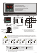
INPUT
+
GND
230V AC +10% -20%
50/60Hz 7VA
7
8
9
10
SN: XXXXXXXXX
ENDA
INDUSTRIAL ELECTRONICS
EI7412-230VAC-AS24
INDICATOR
ALARM
AC 250V 8A
RESISTIVE LOAD
1
2
AUXILIARY
SUPPLY OUT
24V 50mA
+
GND
3
4
OUT
AC 250V 8A
RESISTIVE LOAD
5
6
INPUT
+
GND
230V AC +10% -20%
50/60Hz 7VA
7
8
9
10
SN: XXXXXXXXX
ENDA
INDUSTRIAL ELECTRONICS
EI7412-230VAC-AS12
INDICATOR
ALARM
AC 250V 8A
RESISTIVE LOAD
1
2
AUXILIARY
SUPPLY OUT
12V 50mA
+
GND
3
4
OUT
AC 250V 8A
RESISTIVE LOAD
5
6
INPUT
+
GND
7
8
9
10
SN: XXXXXXXXX
ENDA
INDUSTRIAL ELECTRONICS
EI7412-24VAC-AS05
INDICATOR
ALARM
AC 250V 8A
RESISTIVE LOAD
1
2
AUXILIARY
SUPPLY OUT
24V 50mA
+
GND
3
4
OUT
AC 250V 8A
RESISTIVE LOAD
5
6
24V AC ±10%
50/60Hz 7VA
INPUT
+
GND
7
8
9
10
SN: XXXXXXXXX
ENDA
INDUSTRIAL ELECTRONICS
EI7412-24VAC
INDICATOR
ALARM
AC 250V 8A
RESISTIVE LOAD
1
2
3
4
OUT
AC 250V 8A
RESISTIVE LOAD
5
6
24V AC ±10%
50/60Hz 7VA
INPUT
+
GND
9
10
SN: XXXXXXXXX
ENDA
INDUSTRIAL ELECTRONICS
EI7412-SM
INDICATOR
ALARM
AC 250V 8A
RESISTIVE LOAD
1
2
3
4
OUT
AC 250V 8A
RESISTIVE LOAD
5
6
9-30V DC / 7-24V AC
±10% 7VA
7
8
INPUT
+
9
ALARM
AC 250V 8A
RESISTIVE LOAD
1
2
9-30V DC / 7-24V AC
±10% 7VA
7
8
AUXILIARY
SUPPLY OUT
8V 50mA
+
3
GND
10
SN: XXXXXXXXX
ENDA
INDUSTRIAL ELECTRONICS
EI7412-SM-AS08
INDICATOR
OUT
AC 250V 8A
RESISTIVE LOAD
5
6
GND
4
4./4 EI7412-E