
User guide


13-36
SDF Backannotation
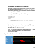
Figure 13-2 illustrates the following series of events:
1. At time 10 output port lout1 transitions to 1. Net int transitions
therefore to X and there is a two time unit delay before this X value
propagates through int to port rightin.
2. At time 15 port lout1 transitions to 0, net int transitions to 0
and port rightin transactions to 0 two time units later.
3. At time 25 both output ports lout1 and botout transitions to 1.
So does net int. Input port rightin transitions to 1 only one
time unit later even though there is a two time unit delay between
lout1 and rightin. The algorithm applied the shortest delay,
one time unit, to the simultaneous transitions at time 25 on lout1
and botout.
Single Source INTERCONNECT Delays
If the INTERCONNECT entries in your SDF file connect no more than
one output or inout port to each of the input or inout ports in your
design you should consider including the
+multisource_int_delays compile-time option that is used for
multisource INTERCONNECT delays.
If you omit the +multisource_int_delays option, VCS uses an
older algorithm that creates a MIPD (Module Input Port Delay) to
model the INTERCONNECT delay. MIPDs only take three delay
values for transitions to 1, to 0, and to Z. If your INTERCONNECT
entry has six delay values, the MIPD only uses the first three so the
Z to 1 delay is the same as the 0 to 1 delay, the 1 to Z delay is the
same as the 0 t0 Z delay, and the Z to 0 delay is the same as the 1
to 0 delay.