
User guide


12-20
Delays and Timing
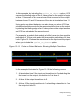
4. At time 16 the input toggles to 0 scheduling a second event on
the output at time 20, a transition to 0. This event also is the trailing
edge of a six time unit wide value 1 pulse so the first event changes
to a transition to X. There is more than one event for different
value changes on the output at time 20, so VCS begins the leading
edge of the X value pulse on the output at this time.
5. At time 20 the output toggles to 0, the second scheduled event at
this time.
If you did not include the +pulse_on_detect option, or substituted
the +pulse_on_event option, you would not see the X value pulse
on the output between times 16 and 20.
Pulse on detect behavior does not just show you when asymmetrical
delays schedule multiple events on the output. Other kinds of events
can cause multiple events on the output at the same simulation time,
such as different transition times on two input ports and different
module path delays from these input ports to the output port. Pulse
on detect behavior would show you an X value pulse on the output
starting when the second event was scheduled on the output port.
Specifying the Delay Mode
It is possible for a module definition to include module path delay that
does not equal the cumulative delay specifications in primitive
instances and continuous assignment statements in that path.
Example 12-11 shows such a conflict.