
User guide


12-17
Delays and Timing
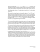
Here you include the +pulse_e/100 and +pulse_r/0 options. The
scheduling problem is that the leading edge of the pulse on the input,
at time 10, schedules a transition to 0 on the output at time 16; but
the trailing edge, at time 11, schedules a transition to 1 on the output
at time 15.
Obviously the output has to end up with a value of 1 so VCS can’t
allow the events scheduled at time 15 and 16 to occur in sequence;
if it did the output would end up with a value of 0. This problem persists
when you enable transport delays and whenever the percentage
specified in the +pulse_r/number option is low enough to enable
the pulse to propagate through the module.
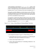
To circumvent this problem, when a later event on the input schedules
an event on the output that is earlier than the event scheduled by the
previous event on the input, VCS cancels both events on the output.
This ensures that the output ends up with the proper value but what
it doesn’t do is indicate that something happened on the output
between times 15 and 16. You might want to see an error message
and an X value pulse on the output indicating there was an undefined
event on the output between these simulation times. You see this
message and the X value pulse if you include the +pulse_on_event
compile-time option, specifying pulse on event behavior, as illustrated
in Figure 12-8. Pulse on event behavior calls for an X value pulse on
the output after the delay and when there are asymmetrical delays
scheduling events on the output that would be canceled by VCS , to
output an X value pulse between those events instead.