
User guide


12-15
Delays and Timing
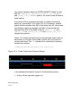
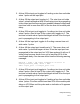
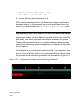
In the example illustrated in Figure 12-6 the following occurs:
1. At simulation time 20 the input port transitions to 0. This schedules
the first event on the output port, a transition to 0 at time 30.
2. At simulation time 30 the input port toggles to 1. This schedules
the output port to toggle to 1 at time 40. Also at simulation time
30 the output port transitions to 0. It doesn’t matter which of these
events happened first. At the end of this time there is only one
scheduled event on the output.
3. At simulation time 36 the input port toggles to 0. This is the trailing
edge of a six time unit wide value 1 pulse. The pulse is equal to
the width specified with the +pulse_e/60 option so VCS
schedules a second event on the output, a value change to 0 on
the output at time 46.
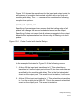
4. At simulation time 40 the output toggles to 1 so now there is only
one event scheduled on the output, the value change to 0 at time
46.
5. At simulation time 46 the input toggles to 1 scheduling a transition
to1 at time 56 on the output. Also at time 46 the output toggles to 0.
There is now only one event scheduled on the output.
6. At time 50 input port toggles to 0. This is the trailing edge of a four
time unit wide value 1 pulse. The pulse is not equal to the width
specified with the +pulse_e/60 option but is equal to the width
specified with the +pulse_r/40 option so VCS changes the first
scheduled event from a change to 1 to a change to X at time 56
and schedules a second event on the output, a transition to 0 at
time 60.
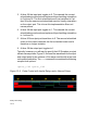
7. At time 56 the output transitions to X and VCS displays the error
message:
Warning: time = 56; Pulse Flagged as error in