
User guide


12-6
Delays and Timing
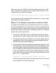
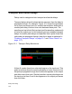
6. At time 14 the output is already 1 so there is no value change.
The narrow pulse on the input between time 9 and 12 is filtered
out. This implementation was devised for these narrow pulses.
There is now no event scheduled for the output.
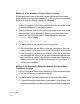
7. At time 15 the input toggles to 0 and this schedules the output to
toggle to 0 at time 20.
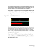
Inertial Delays for Module Path Delays and INTERCONNECT
Delays
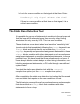
The implementation of inertial delays for module path delays and SDF
INTERCONNECT delays is that if the event scheduled by the leading
edge of a pulse is scheduled for a later simulation time or, in other
words, has not yet occurred, the event scheduled by the trailing edge,
at the end of the specified delay and at a new simulation time, replaces
the event scheduled by the leading edge. All narrow pulses are filtered
out.
Note:
- SDF INTERCONNECT delays follow this implementation if you
include the +multisource_int_delays compile-time
option. If you do not include this option, VCS uses an MIPD to
model the SDF INTERCONNECT delay and the delay uses the
inertial delay implementation for MIPDs. See
"INTERCONNECT Delays" on page 13-32.
- VCS enables more complex and flexible pulse control
processing when you include the +pulse_e/number and
+pulse_r/number options, see "Pulse Control" on page
12-7.