
User guide


12-5
Delays and Timing
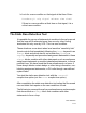
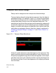
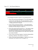
Figure 12-3 Gate Terminal Waveforms
In the example illustrated in Figure 12-3, the following occurs:
1. At time 3 the input terminal changes to 0. This is the leading edge
of a three time unit wide pulse. This event schedules a value
change to 0 on the output terminal at time 8 because there is a
#5 delay specification for the gate.
2. At time 6 the input terminal toggles to 1. This implementation
keeps the scheduled transition on the output terminal at time 8
but alters the value change to a value of 1.
3. At time 8 the output terminal transitions to 1. This transition might
be unexpected because all pulses on the input have been
narrower than the delay but this is how this implementation works.
There is now no event scheduled on the output and a new event
can now be scheduled.
4. At time 9 the input terminal toggles to 0 and the implementation
schedules a transition of the output to 0 at time 14.
5. At time 12 the input terminal toggles to 1 and the value change
scheduled on the output at time 14 changes to a 1.