
User guide


6-30
VPD and EVCD File Generation
Conceptual Example of Using VPD System Tasks
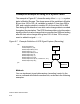
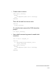
The example in Figure 6-7, shows the entry of the $vcdplus system
tasks in Module B scope. The dump saves all the variables in Module
B from time 100 to 300, all variables in module C from time 200 to
500, and a single variable in module D1.clk from time 600 to 900.
Zero delay glitch detection is on while value change data is recorded
throughout the simulation. The VPD file stores delta cycle information
starting at the first value change that occurs after time 200 and ending
after the last value change during time 300. At time 700 a unique
event is added to signal D.clk.
Figure 6-7 Example Definition of VPD Signal Capture (Recording)
Methods
You can implement signal data capture (recording) control in the
source code and at the shell command line, as shown in the following
examples.
fork
#0 $vcdplusglitchon;
#100 $vcdpluson (1,B);
#200 $vcdplusdeltacycleon;
#200 $vcdpluson (1,C);
#300 $vcdplusdeltacycleoff;
#300 $vcdplusoff (1,B);
#500 $vcdplusoff (1,C);
#600 $vcdpluson (D.clk);
#700 $vcdplusevent (D.clk, "UserEvent", "IS");
#900 $vcdplusoff (D.clk);
join
Module B
Module C Module D
Module A