
User guide


24-200
SystemVerilog Testbench Constructs
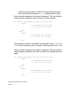
initial
begin
@ (cb1); //synchronising with clocking event
cb1.a <= 0; //drive at first posedge
cb1.b <= 0; //drive after skew on first posedge
##2 cb1.a <= 1;
##1 cb1.b <= 1; //drive after 3 clock cycles
end
The expression cb1.a (and cb1.b) is referred to as the
clockvar_expression in the SystemVerilog LRM 3.1a (see page 190).
Note:Synchronous drives with a blocking cycle delay is supported.
However, a synchronous drive with an intra cycle delay is not yet
supported.
Drive Value Resolution
When the same net is an output from multiple clocking blocks, then
the net is driven to its resolved signal value. When the same variable
is an output from multiple clocking blocks, then the last drive
determines the value of the variable.
Clocking Blocks in SystemVerilog Assertions
You can enter a clocking block as a clock signal for an assertion,
property, or sequence. When you do the clocking event in the clocking
block becomes the clock signal. The following is an example of a
clocking block in an assertion:
clocking ck1 @(posedge clk) ;
.
.
.
endclocking