
User guide

24-193
SystemVerilog Testbench Constructs
end
endprogram
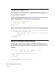
The output of this program is:
0 x
30 0
130 0
150 1
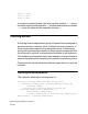
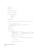
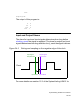
Input and Output Skews
The skew for input and inout signals determines how long before
clocking_event the signal is sampled. The skew for output and inout
signals determines how long after the clock_event the signal is driven.
Figure 24-3 Driving and sampling on the negative edge of the clock
For more details see section 15.3 of the SystemVerilog LRM 3.1a.
Clock
input skew output skew
input signal output signal
sampled here driven here