
User guide


18-4
Translating VCD and VCD+
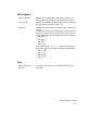
Mapping EVCD to VCD+ Signals
In the conversion, each EVCD port maps to two new VCD+ signals:
a Test Fixture (TF) signal and a Device-Under-Test (DUT) signal.
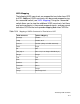
Table 18-1, Table 18-2, and Table 18-3 show the mapping of values
in the EVCD file to values in the VCD+ file.
Table 18-1 Mapping In Input Mode (TF Drives)
EVCD Value Maps To VCD+ TF To VCD+ DUT
D low St0 HiZ
U high St1 HiZ
N unknown StX HiZ
Z tri-state SmZ HiZ
d low (2 or more drivers active) Su0 HiZ
u high (2 or more drivers active) Su1 HiZ
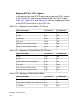
Table 18-2 Mapping In Output Mode (DUT Drives)
EVCD Value Maps To VCD+ TF To VCD+ DUT
L low HiZ St0
H high HiZ St1
X unknown (value not important) HiZ Stx
T tri-state HiZ SmZ
l low (2 or more drivers active) HiZ Su0
h high (2 or more drivers active) HiZ Su1
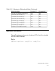
Table 18-3 Mapping in Bidirectional Mode
EVCD Value Maps To VCD+ TF To VCD+ DUT
0 low (Both TF and DUT active with 0 value) St0 St0
1 high (both TF and DUT active with 1 value) St1 St1
? unknown StX StX