Alpine Screen Kit 36"W X 54"H 60 min Approximate assembly time for 2 panels Scan the QR code for an assembly video ASSEMBLY INSTRUCTIONS www.encloscreens.com EC18012 (WHITE COLOR) EC18013 (CHARCOAL COLOR) VER.
EC18012 / EC18013 ASSEMBLY INSTRUCTIONS GENERAL INFORMATION IMPORTANT j j j j MISSING OR DAMAGED PARTS? Check the inside of the larger pieces in your box for other materials packed inside. When assembling components, place on a non-abrasive surface (i.e. shipping box) to avoid scratching. We recommend an area approximately 5’x 8’ for unobstructed assembling. You should not need to use excessive force when assembling components.
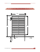
ASSEMBLY INSTRUCTIONS EC18012 / EC18013 Detailed Product Dimensions & Specifications 36 in 0.9 0.9 in 54 in 47.5 in 14in 14 in www.encloscreens.com 3.5 in in 3.
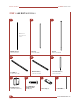
EC18012 / EC18013 ASSEMBLY INSTRUCTIONS STEP 1: LAY OUT MATERIALS B A C Note: Holes through both walls. Middle Post (2) 5/8" x 1" x 50 3/8" Slat (44) 1/4" x 1 1/4" x 34" D Post (4) 7/8" x 1 1/2" x 53 7/8" E F Ground Stake (4) 3/4" x 1 1/4" x 20" Bottom Rail (2) 1 1/2" x 1 1/2" x 36" Top Rail (2) 1 1/2" x 1 1/2" x 36" G H I J Rail End Cap (8) (4 installed; 4 loose) 3/4" Self-Drilling Stainless Steel Screw (28) Joiner Clip (2) 1/8" Drill Bit (1) 4 www.encloscreens.
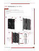
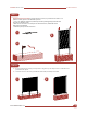
ASSEMBLY INSTRUCTIONS EC18012 / EC18013 STEP 2: ASSEMBLING THE FIRST PANEL STEP 2.1 1. Insert (22) Slats (B) through the Middle Post (A). 2. Insert (1) Post (C) over one end of the slats until they hit the back wall of the post. 3. Insert (1) post over the ends of the slats until they hit the back wall of the post. 1 A 2 B C 3 Note: This will be the top of the screen. Note: Push the first post against a wall to prevent the slats from falling out of the post. www.encloscreens.
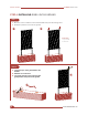
EC18012 / EC18013 ASSEMBLY INSTRUCTIONS STEP 2.2 1. Insert (1) Bottom Rail (E) until the bottom of the middle post hits the bottom rail wall. Do not install the screws yet. 2. Insert (2) Ground Stakes (F) up the post until the pre-drilled holes in the anchor and the side of the posts align. 3. Drive (4) total 3/4" Self-Drilling Stainless Steel Screws (H) in to the pre-drilled holes to secure the anchors. 1 2 Align 3 F E H STEP 2.3 1.
ASSEMBLY INSTRUCTIONS EC18012 / EC18013 STEP 2.4 1. Insert (1) Top Rail (D) over the posts until the pre-drilled holes on the post and the top rail align. 2. Drive (4) total 3/4" 3/4" self-drilling stainless steel screws into the pre-drilled holes in the top rail. 1 D 2 Align STEP 3: ASSEMBLING THE SECOND PANEL STEP 3.1 Repeat steps 2.12.4 to assemble the second screen. www.encloscreens.
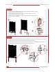
EC18012 / EC18013 ASSEMBLY INSTRUCTIONS STEP 4: INSTALLING PANELS IN THE GROUND STEP 4.1 1. Move the screen to its final location and mark where the posts meet the ground. 2. Attempt to push the screen into the ground. 1 2 Push down on posts with both hands. STEP 4.2 5.3 1. Loosen the top 6" of the ground with a claw hammer. 2. Add water to loosened soil. 3. Use a block of wood to protect the post and gently hammer each post into the ground. 3 2 1 8 www.encloscreens.
ASSEMBLY INSTRUCTIONS EC18012 / EC18013 STEP 4.3 Optional in hard ground: If your ground is too hard, or you have more than 3 or 4 panels to install, please consider these options: 1. Use a 1¾” diameter auger bit (commonly used for planting tulips) as illustrated ($15-$20 on Amazon.com). 2. Drill a hole about 12” to 16” deep at the desired location, and fill the holes with water as illustrated. 3. Push the panel posts into the holes. 1 3 2 STEP 4.4 5.3 1.
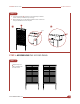
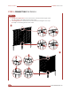
EC18012 / EC18013 ASSEMBLY INSTRUCTIONS STEP 5: CONNECTING THE PANELS STEP 5.1 1. Straight Line Application: Connect the screens as shown below using the Joiner Clips (I) and (4) 3/4" self-drilling stainless steel screws. 2. Corner Application: Connect the screens as shown below using the Joiner Clips (I) and (4) 3/4" self-drilling stainless steel screws. 1 I 2 I 10 www.encloscreens.
www.encloscreens.com support@encloscreens.com 704-892-5222 877-234-6196 6935 Reames Rd. Ste. K. Charlotte, NC 28216 ASSEMBLY INSTRUCTIONS EC18012 (WHITE COLOR) EC18013 (CHARCOAL COLOR) VER.