LPe12000 and LPe12002 HBA Installation Manual Last updated January 29, 2008
Copyright© 2008 Emulex Corporation. All rights reserved worldwide. No part of this document may be reproduced by any means nor translated to any electronic medium without the written consent of Emulex Corporation. Information furnished by Emulex Corporation is believed to be accurate and reliable. However, no responsibility is assumed by Emulex Corporation for its use; or for any infringements of patents or other rights of third parties which may result from its use.
Table of Contents Introduction................................................................................................................................................... 1 Major Features ................................................................................................................................ 1 Compatibility .................................................................................................................................... 1 Prerequisites........................
Introduction This manual describes the Emulex® LPe12000 and LPe12002, 8 gigabit per second (Gb/s) Fibre Channel (FC) to Peripheral Component Interconnect Express (PCIe) host bus adapters (HBAs). They feature a revolutionary design with integrated ARM-1156 cores, integrated SERDES, integrated SRAM, and external Double-Data Rate (DDRII SRAM) memory structure. The Emulex LPe12000 is a singlechannel adapter. The LPe12002 is a dual-channel adapter.
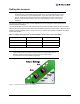
Setting the Jumpers Caution: Emulex LightPulse® HBAs contain electronic components that can be damaged by static electricity through an electrostatic discharge (ESD) event. To prevent ESD damage, maintain constant contact with any grounded metal surface. A grounding wrist strap is useful for this purpose. Handle the card carefully at all times and preferably by the edges. Avoid touching electronic components and keep the card in the original packaging until you are ready for installation.
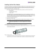
Installing the Host Bus Adapter The Emulex LPe12000 and LPe12002 host bus adapters (HBAs) use a removable optical transceiver. If you need to change the bracket for HBA installation, you must first remove this transceiver from its housing (cage). This document explains how to install the HBA and, if necessary, how to remove the transceiver and bracket safely. To install the HBA: 1. Each HBA is shipped with several numbers clearly marked on the board.
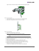
Figure 3 shows one transceiver partly extracted and the other latched in place Figure 3: Removing a transceiver 7. Observing ESD precautions, store the transceiver in an ESD-safe place. 8. Remove the mounting bracket screws from the top of the HBA. Figure 4: Removing the Bracket 9. Remove the bracket and store it for future use. 10. Align the new mounting bracket tabs with the holes in the HBA. Note: Be careful not to push the bracket past the transceiver housing's grounding tabs.
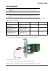
Attaching Media Note: The HBA will not allow normal data transmission on an optical link unless it is connected to another similar or compatible laser product (that is, multimode to multimode.) Note: The HBA will not automatically downgrade to the required FC speed based on cable length. You must downgrade the speed with the appropriate utility or link errors may occur. Use multimode fiber optic cable, with short-wave lasers, that adheres to the following specifications: Table 5.
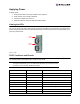
Applying Power To apply power: 1. Verify that the HBA is securely installed in the computer. 2. Verify that the correct media is attached. 3. Plug in the computer and turn it on. 4. Watch the LEDs for Power On Self Test (POST) results. Viewing the LEDs You can see green and yellow LEDs through openings in the HBA's mounting bracket. The green LED means firmware operation and the yellow LED means port activity. Each port has a corresponding set of green and yellow LEDs.
Table 8.
References Specifications Table 9. LPe12000 and LPe12002 Specifications Parameter Range Media Interface The controller interfaces to the physical media through an FC-0 Media Interface (FC-PI compliant transceiver), and then connects through dual optical fiber LC connectors. Physical Dimensions Low-profile MD2 form factor, 6.600 inches by 2.713 inches, and accommodates both the full-height and low-profile bracket. Power Requirements LPe12000 • 1.1 watts (typical) @ +3.3 V ±9% • 2.
FCC and Regulatory Notices LPe12000 and LPe12002 HBA Models This device complies with Part 15 of the FCC Rules. Operation is subject to the following two conditions: (1) This device may not cause harmful interference, and (2) this device must accept any interference received, including interference that may cause undesired operation. Responsible Party: Jim McCluney, Chief Executive Officer Emulex Corporation (714) 662-5600 3333 Susan St. Costa Mesa, CA.
Notice for Taiwan and Translations (BSMI) Translation: This equipment is a Class A ITE, and operation of this equipment in a residential area is likely to cause harmful interference, in which case users will be required to correct the interference at their own expense. Notice for South Korea and Translations (MIC) Translation: Class A Equipment: Please note that this equipment has been approved for business purposes with regards to electromagnetic interference.
LPe12000 and LPe12002 Hardware Installation Manual Page 11
Laser Safety Notice This laser safety information contains certification and product information covering laser products known as optical small form factor transceivers incorporated in Emulex LightPulse host adapters. The small form factor transceiver is the primary cable connection mechanism for any optical port on the host adapter. This data is not intended to be a replacement for any safety regulations and standards; relevant safety documents should always be consulted if necessary.
Alternatively, at the discretion of the manufacturer, the same statement may be included in user information. If a label is used, an example of the IEC Class 1 information label that is suitable for most European countries is shown below. The label consists of black printing on a white background. Languages represented on this label are English, German, Finnish and French, and they represent the minimum set for acceptance of a Class 1 product in most European countries.
factor transceiver, and the system level documentation and labeling. Copies of the certificate of conformity for any small form factor transceiver sold by Emulex can be obtained upon request from Emulex Corporation, Costa Mesa.